Table of Contents
Pin count and pitch are only the first filter for a flexible flat cable (FFC) or flexible printed circuit (FPC) connector replacement. A 40-position, 0.5 mm-pitch part can fit the board outline and still make no electrical connection if the cable’s exposed conductors face away from the contacts. A different finished cable thickness can produce another deceptive result: the latch closes, but contact pressure or retention is inadequate.
For FFC and FPC interfaces, the purchased item is part of a mating system. Review the board connector, cable end and assembly motion together. That is especially important when an older display, operator panel or sensor board must keep its released cable assembly.
What defines an FFC or FPC connector replacement?
A replacement must match the electrical contact arrangement and the mechanical mating geometry of the released assembly. Pin count and pitch are necessary filters, but the contact side, cable-end dimensions, insertion direction, actuator and board footprint determine whether the candidate can actually be used.
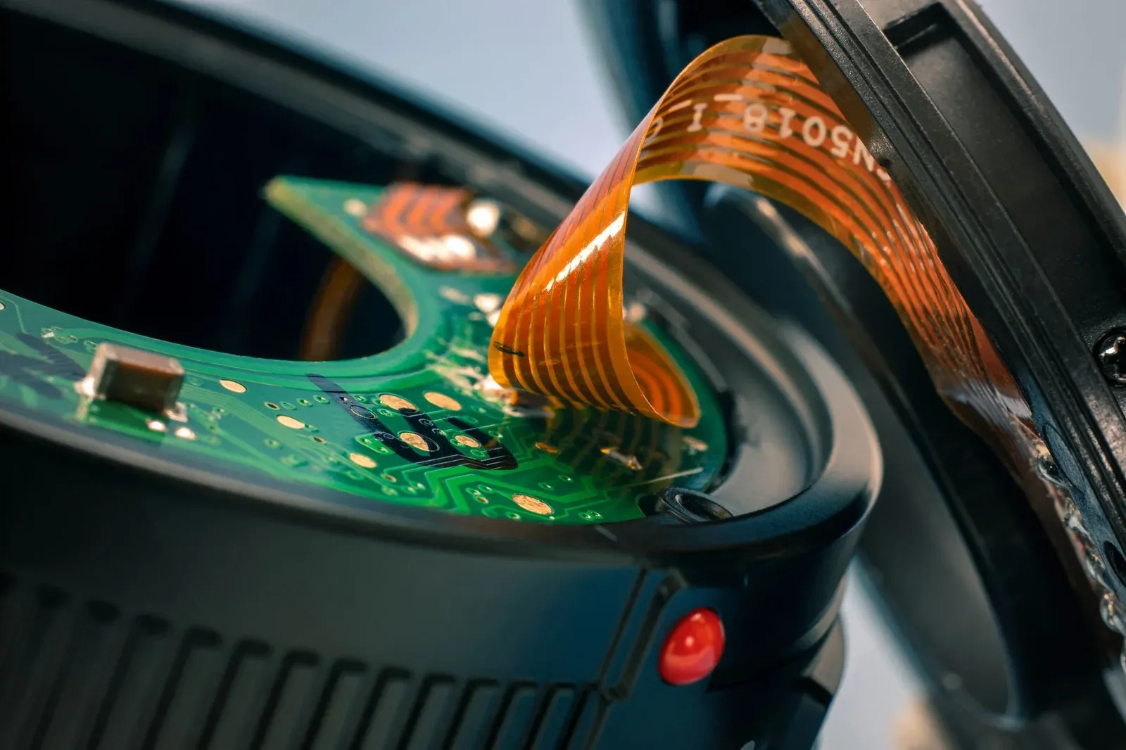
FFC generally uses parallel flat conductors within a flexible cable construction, while an FPC can carry patterned circuit traces and more complex geometry. A connector may accept both, but only within the mating requirements in its drawing. The label “FFC/FPC” does not mean every cable end is compatible.
Hirose’s FH34 series overview, for example, specifies 0.5 mm pitch, 0.3 mm FPC/FFC thickness and top-and-bottom contacts. Those are properties of that series, not defaults for all 0.5 mm connectors. Follow the exact order code to its drawing, position count and mounting details before using it in a cross-reference.
Do not infer overall cable width from pin count alone. For a 40-position cable at 0.5 mm pitch, the center-to-center span between the first and last conductor is (40 − 1) × 0.5 = 19.5 mm. Total cable width also includes conductor width and edge margins. The cable drawing, rather than this span calculation, controls the finished outline.
How do contact side and pin numbering affect compatibility?
Match the exposed conductor face to the connector’s contact location, then trace pin numbering through both ends of the cable. Flipping a cable to reach a different contact side can change the assembled connection or violate its mechanical routing requirements.
Create a simple connector-and-cable view with the PCB reference surface, insertion direction, exposed copper face and pin 1 marked. Compare that view with the proposed connector’s mechanical drawing. Descriptions such as “top contact” become ambiguous when a board is inverted or a distributor’s photograph is viewed from the rear.
For a cable assembly with connectors at both ends, document the actual net mapping. Two cables can have identical length and pitch but expose conductors on different faces at their ends. Verify continuity against the schematic before applying power, particularly where adjacent pins carry supply rails and signals.
A replacement with dual contacts does not automatically solve the pin-mapping problem. It may change which conductor face can be contacted, but cable orientation and end-to-end connectivity still belong to the system drawing.
Which thickness should be compared with the connector specification?
Compare the finished mating-end thickness, including the relevant conductor, insulation and reinforcement stack, with the connector’s permitted range. The flexible cable body thickness alone may exclude the stiffener that controls insertion and contact pressure.
The Molex FFC product specification treats cable-end geometry, exposed contacts and reinforcement as defined features. Obtain the comparable drawing for the actual cable being retained; a generic catalog description is insufficient for tolerance comparison.
Suppose the connector drawing permits a finished mating-end thickness of 0.27–0.33 mm. A proposed finished cable end of 0.20 ± 0.02 mm spans 0.18–0.22 mm and falls outside that requirement. A successful room-temperature continuity check would not establish adequate contact force or retention. Neither the range nor the example is a universal connector specification.
Also compare the exposed conductor length, stiffener length, insertion stop and cable width tolerance. A cable that reaches the housing stop may still place insufficient conductor area under the contacts. If the drawing is unavailable, measure representative released assemblies to support investigation, but resolve the controlled specification before approving a production alternate.
Mechanical access and assembly behavior
The connector must remain usable after surrounding components, shields and the enclosure are installed. Compare the open-actuator envelope, cable approach angle and the space needed for an operator or assembly fixture. Matching the closed connector height does not establish this clearance.
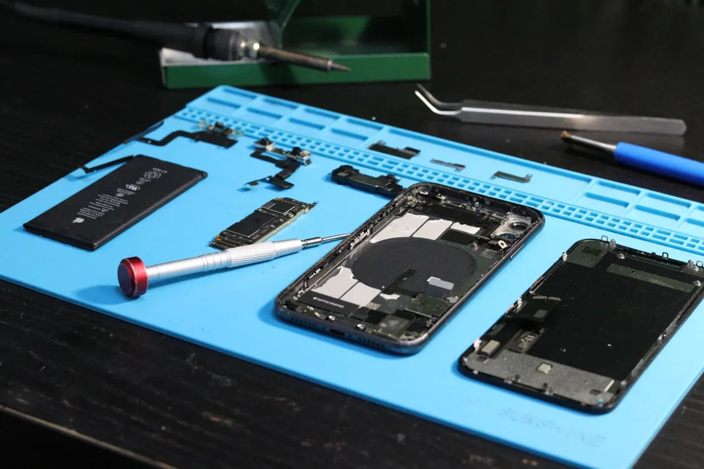
Follow the manufacturer’s operation sequence. Hirose’s FH34 handling guidelines explain actuator and insertion handling for that design. A different series may use a different latch motion; work instructions must change when the mechanism changes.
| Assembly feature | Compare on the drawings and samples | Disposition if different |
|---|---|---|
| PCB land pattern | Pad positions, hold-downs and solder-joint geometry | Treat as a board-layout change |
| Cable mating end | Thickness, exposed length, width and reinforcement | Revise the cable or reject the candidate |
| Actuator clearance | Open height, travel and access direction | Check the complete assembly sequence |
| Cable routing | Bend location, pull direction and enclosure contact | Adjust strain relief and repeat mechanical tests |
| Electrical contact | Net mapping, resistance and current conditions | Resolve mapping or rating mismatch before power-up |
Do not use the actuator to pull a partly inserted cable into place. Compare insertion depth marks or other assembly controls where available, and examine samples for uneven seating and damaged conductors. For environments with vibration or repeated servicing, qualify the installed cable routing and retention rather than evaluating a loose connector in isolation.
Releasing an alternate for production
The qualification record should pair a specific connector order code with a specific cable drawing and PCB revision. Include continuity, contact resistance under the agreed conditions, retention and the application’s environmental checks. A supplier offer that lists only pitch and position count is not a controlled replacement; require the exact order code, cable drawing and mating-cycle evidence. Broader material and durability comparisons belong in the connector-alternate qualification guide.
For the component-alternative evaluation, classify the result precisely: same-board replacement, replacement requiring a new cable, or a connector requiring PCB changes. Those outcomes have different tooling, validation and purchasing implications even when the unit prices are similar.
Keep accepted samples and dimensional records tied to the released pair. If a future source offers an apparently equivalent connector, the comparison can begin with the actual contact geometry and mating system instead of repeating a pitch-only search.
Frequently Asked Questions (FAQ)
Can a broken FPC connector actuator be replaced independently?
Only if the connector manufacturer supplies and approves that repair for the exact series. Actuators that look similar may have different pivots, cam profiles and retention geometry. Otherwise use the approved connector replacement and board-rework process.
Does dual-contact construction allow any cable orientation?
No. Dual-contact construction may accept contacts on either face within the specified cable geometry, but it does not validate the circuit's pin mapping, cable thickness, reinforcement or insertion direction. Review the connector and cable drawings together.
Should connector mating life equal the expected number of factory tests?
Budget factory insertion, retest, rework and field-service cycles together, with the project's required margin. Verify that the manufacturer's mating-cycle specification uses conditions relevant to the intended cable and assembly process.