Table of Contents
A connector alternate must reproduce a mechanical contact system, not just a pitch and outline. Small differences in spring geometry, plating stack, housing material, latch position, and terminal retention can change resistance, wear, assembly yield, and behavior after vibration or corrosion.
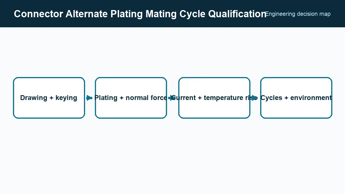
Use staged qualification so a basic fit failure stops the program before environmental testing. Keep the exact mating half, wire, crimp tooling, and PCB footprint in the test definition.
What must match beyond connector pitch and pin count?
A connector alternate must preserve contact engagement, keying, latch geometry, stack height, tolerances, and the board or cable interface, not just pitch and pin count. Compare row spacing, keep-outs, coplanarity, pin length, and hole or pad dimensions at minimum engagement before committing to environmental testing.
Compare contact base alloy, heat treatment, normal force, contact style, housing resin, flammability, temperature rating, and terminal retention. A housing that fits can still have different reflow limits or creepage dimensions.
Inspect samples by measurement rather than overlaying catalog drawings visually. Include board-mounted and cable-mounted conditions, strain relief, and permitted misalignment.
Compare the complete plating system
Record finish material and thickness in the contact zone and termination zone, plus nickel or other underplate. Gold flash, selective gold, tin, and palladium-nickel systems have different wear, fretting, soldering, and galvanic behavior.
Samtec’s connector-plating FAQ, accessed September 24, 2026, explains the roles of contact finish, underplate, and application conditions. Do not compare one gold-thickness number while ignoring the contact’s normal force and wipe, which determine how the surfaces interact.
Mixed finishes can be risky. For example, mating tin and gold can produce wear debris and an interface different from either qualified homogeneous pair. Obtain a manufacturer’s compatibility statement or test the actual pair.
Measure electrical and thermal behavior
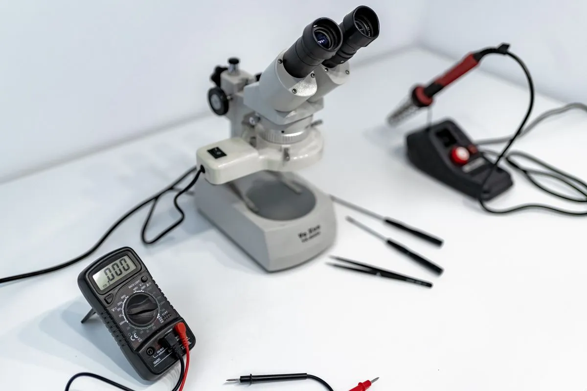
Begin with low-level contact resistance using a four-wire method and dry-circuit limits. Measure initial values and change after durability and environmental stresses. Insulation resistance and dielectric withstand address separate paths through the housing.
For power contacts, load the intended number of adjacent positions and measure temperature rise at the worst ambient and airflow. Published current ratings depend on conductor size, contact count, PCB copper, and allowed temperature rise. Evaluate voltage drop and current sharing when contacts are paralleled.
For high-speed links, preserve impedance, insertion loss, return loss, crosstalk, and skew requirements. A DC-compatible alternate may alter the launch or dielectric geometry enough to close the channel margin.
How should connector durability and environmental tests be sequenced?
Sequence connector tests to represent the product’s wear and exposure history; mating wear before corrosion can expose a weakness that separate tests miss. Define the actual mating pair, required cycles, shock, vibration, thermal cycling, humidity, and corrosive exposure from the application rather than applying every available test.
Samtec’s connector reliability guide, accessed September 24, 2026, connects contact geometry and plating with shock, vibration, and corrosive exposure. Select stresses from the product requirement rather than applying every test indiscriminately.
Monitor discontinuities during vibration when an intermittent connection is the risk. A post-test resistance reading can miss brief opens. After exposure, inspect wear tracks, fretting debris, corrosion, cracked latches, backed-out terminals, and housing deformation.
Approve the process as well as the catalog part
For crimp terminals, qualify wire gauge, insulation diameter, strip length, applicator, crimp height, pull force, and cross sections. For board connectors, validate placement, reflow or wave soldering, coplanarity, solder joints, wash process, and repair.
The approval package should lock both mating part numbers, drawings and revisions, materials, plating stack, approved tooling, current and temperature-rise conditions, electrical limits, mating cycles, environmental sequence, and inspection criteria. Incoming inspection can then verify critical dimensions, marking, plating documentation, and lot traceability without pretending that visual similarity proves contact reliability.
Frequently Asked Questions (FAQ)
Is the same connector plating thickness enough to prove equivalence?
No. Base material, underplate, finish composition, porosity, contact geometry, normal force, wipe, and environmental exposure all affect contact performance.
Why is low-level contact resistance measured before high-current testing?
A dry-circuit measurement limits voltage and current so the test does not electrically clean or weld surface films. Higher-energy measurements can mask the contact condition being evaluated.
Does a connector's published mating-cycle rating apply with any mating half?
No. Durability is normally specified for a defined compatible pair, plating system, and test method. Mixed manufacturers or finishes need explicit qualification.