Table of Contents
Single-pair Ethernet is attractive when a field instrument needs more useful data than its existing link can carry without adding a second cable for power. The purchase decision, however, is a complete link: host interface, PHY, cable, power coupling and the device at the far end.
For 2027 industrial designs, 10BASE-T1L is a practical candidate to evaluate using available silicon and reference platforms. Keep that evaluation tied to the installed channel and application workload instead of treating every single-pair Ethernet part as interchangeable.
Which 10BASE-T1L device fits the host processor?
Use a PHY when the host provides a compatible Ethernet MAC interface. Consider a MAC-PHY when a suitable serial interface is available but the host lacks the required MAC. That choice changes both hardware and software work.
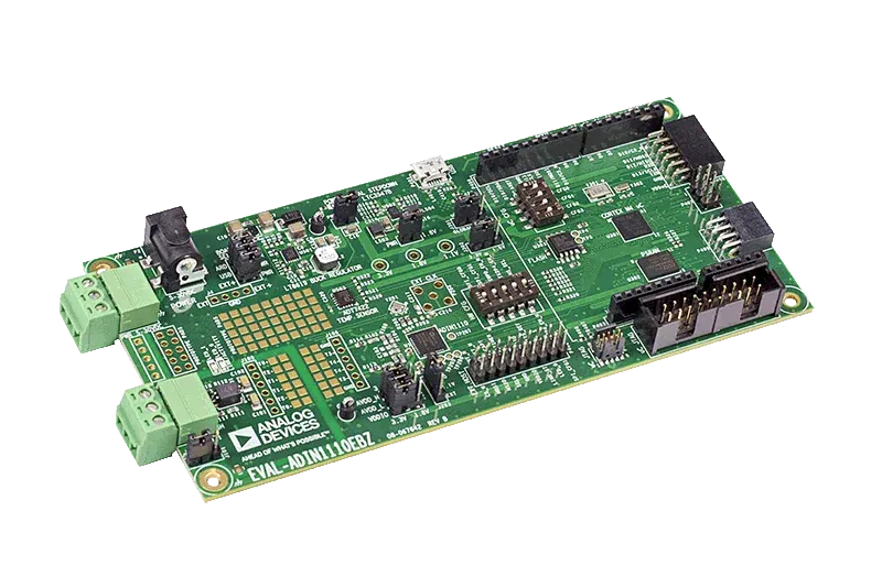
For example, Analog Devices’ ADIN1110 integrates a MAC and exposes data through SPI for a 10 Mb/s 10BASE-T1L link. Its product documentation includes link diagnostics and configurable transmit levels. In an ADIN1110 vs ADIN1100 comparison, the decisive difference is the host architecture: ADIN1100 is a PHY with MII, RMII and RGMII interfaces to an external MAC. Carry that data path, driver support and buffering requirement into the BOM review; these devices are not interchangeable serial peripherals.
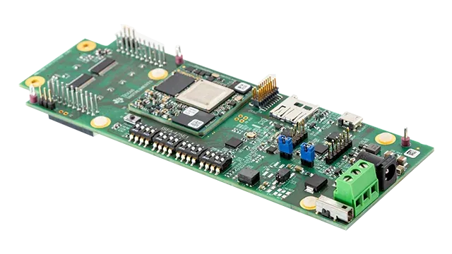
TI’s TIDA-010261 reference design takes a different route, pairing an AM2434 MCU with a DP83TD510E PHY and a power-over-data-line implementation. The design is useful evidence of an architecture and supporting circuitry; TI identifies the assembled reference board as a validation platform not offered for sale.
A 10 Mb/s line rate is not ten megabits of application payload available every second under every workload. Include Ethernet overhead, host transfers, software scheduling and traffic bursts. If a serial host cannot empty buffers quickly enough, a good cable link can still lose application data.
What must match for single-pair Ethernet power delivery?
Match the sourcing and powered-device class, voltage range, classification behavior and coupling network. The data link and power path must both work at startup and at the worst required operating point.
TIDA-010261 specifies Type E, Class 12 PoDL and an auxiliary 24 V supply. That is a defined implementation, not evidence that any generic two-wire power source can replace its power sourcing equipment.
| BOM decision | Evidence to obtain before selecting a part |
|---|---|
| PHY and host | Exact interface, supported driver and data-buffer behavior |
| Power class | Compatible source and load, classification and startup sequence |
| Cable | Required reach, loop resistance, insertion/return loss and environmental rating |
| Coupling and protection | Values and ratings from the validated PHY/power architecture |
| Connector | Mating compatibility, shield arrangement and installation requirements |
| Diagnostics | Link-quality, cable-fault and power-fault behavior exposed to the host |
Treat the maximum allowed voltage drop and the load’s startup demand as purchase requirements. A sensor that runs from a bench supply can still fail when powered through a long cable.
How should cable resistance affect the power budget?
Calculate the voltage and loss at the load, using the complete loop resistance and maximum relevant current. Then check the actual powered-device input limits and startup behavior.
For an illustrative 24 V source, 20-ohm cable loop and 0.2 A load current, the cable drop is 4 V and the cable dissipation is 0.8 W. The load receives approximately 20 V and 4 W before conversion losses. These values describe one electrical operating point, not a power-class limit.
A constant-power load can draw more current as its input voltage falls, increasing cable loss further. Evaluate the coupled load and cable behavior rather than holding the nominal current fixed throughout the whole operating range. Include connector resistance, source tolerance and the cable’s hot resistance.
If the load cannot start within the supported power envelope, investigate the power class, channel or startup profile. Adding bulk capacitance may increase inrush and make startup worse, so the power controller’s requirements must govern that change.
Test the installed link as a system
Run the intended data stream over the specified cable length with connectors and shielding representative of installation. Exercise cold start, supply interruption and simultaneous peak load. Capture link drops, retries or application losses alongside power measurements and diagnostic counters.
Where a field device operates in a hazardous location, the complete system requires its applicable assessment. A PHY described as suitable for intrinsic-safety applications does not certify the assembled instrument.
For a long-service-life sensor platform, keep the approved PHY, power controller, magnetics or coupling parts, connector and driver revision together. Requalify the affected link when one changes. Our industrial Ethernet controller sourcing guide addresses legacy controller continuity; this review concerns a new single-pair physical link.
An industrial sourcing inquiry should include the intended link partner, host interface, cable length, power class and deployment date. Those inputs let suppliers compare a complete supported BOM instead of quoting unrelated parts carrying the same Ethernet label.
Frequently Asked Questions (FAQ)
Can a 10BASE-T1L device communicate directly with 10BASE-T1S?
No. These are different physical-layer implementations with different link arrangements. Specify the intended PHY at both ends; the single-pair Ethernet label alone is insufficient.
Does a single-pair Ethernet PHY provide power over the cable?
Not by itself. Power delivery needs the appropriate power sourcing and powered-device circuitry, coupling network, protection and class agreement.
Can existing sensor cable always be reused?
No. Evaluate the installed cable's electrical characteristics, length, connectors, shielding and environment. A continuity check alone does not establish a reliable Ethernet and power channel.