Table of Contents
A flyback transformer stores energy in a gapped core and releases it into the output during the off-time. That is why a replacement with the same footprint and nominal inductance can still change the converter’s current waveform, clamp loss and auxiliary supply.
Treat a flyback transformer design as part of the converter. The drawing and test conditions are as important as the catalog value.
Which parameters must match the converter?
Compare primary inductance, turns ratios, winding polarity, leakage, current capability, losses and insulation construction. Include every winding used by the controller or load, not just the main output.
| Parameter | Why the replacement can behave differently | RFQ evidence to require |
|---|---|---|
| Primary inductance and tolerance | Changes current slope and energy at a given peak current | Nominal, tolerance, test frequency and amplitude |
| Turns ratio and polarity | Changes reflected voltage, duty-cycle requirements and rectifier stress | Ratio, polarity and winding order |
| Auxiliary winding | Can shift controller supply, regulation sensing or startup behavior | Turns, voltage and loading |
| Leakage inductance | Changes turn-off energy that the clamp or recovery circuit must handle | Measurement setup, shorted windings, frequency |
| Hot winding resistance | Changes conduction loss and temperature rise | DCR at temperature and wire gauge |
| Core and gap | Affects saturation and losses over the operating range | Core material, gap and saturation data |
| Insulation and pinout | Determines electrical separation and physical compatibility | Construction, distances and pinout drawing |
Coilcraft’s flyback transformer guide explains the energy-storage role of the gapped magnetic structure. Unlike a simple ideal transformer comparison, the flyback design depends on how energy is stored and released during each switching cycle.
Specify the controller, topology variant, input range, outputs, switching range and current limit in the RFQ. A transformer optimized for one discontinuous-mode operating point may be unsuitable for a converter running with continuous current or a different control strategy.
Primary inductance sets stored energy
At a specified peak current, stored energy is proportional to inductance: E = ½LI². This is a useful comparison when the operating mode and control limits are stated.
| Primary inductance | Stored energy at 2 A peak | Ideal transferred power at 100 kHz |
|---|---|---|
| 60 µH | 0.12 mJ | 12 W |
| 80 µH | 0.16 mJ | 16 W |
| 100 µH | 0.20 mJ | 20 W |
| 120 µH | 0.24 mJ | 24 W |
For an illustrative discontinuous-conduction cycle starting at zero current, a 100 microhenry primary at 2 A stores 0.2 mJ. If all that energy is transferred once per cycle at 100 kHz, the ideal transferred power is 20 W, before losses. An 80 microhenry replacement at the same 2 A peak stores 0.16 mJ, corresponding to 16 W under the same ideal assumptions. It cannot be declared equivalent by package size alone.
The comparison changes if on-time rather than peak current is held constant: a lower inductance produces a steeper current ramp. Review the actual controller behavior and operating modes, including current-limit tolerance and startup, before using either calculation as a design conclusion.
TI’s inductor and flyback magnetics design material provides the underlying design context. A production alternate still requires its actual current waveforms and temperatures to be checked.
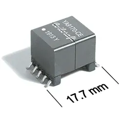
Why does leakage matter in the quote?
Leakage energy contributes to the turn-off transient and the burden on the clamp or recovery network. A lower transformer price can be offset by additional loss, component stress or a changed clamp design.
| Leakage inductance | Energy per cycle at 2 A | Energy rate at 100 kHz |
|---|---|---|
| 1 µH | 2 µJ | 0.2 W |
| 2 µH | 4 µJ | 0.4 W |
| 3 µH | 6 µJ | 0.6 W |
| 5 µH | 10 µJ | 1.0 W |
Using E = ½LleakI², a 1 microhenry leakage inductance at 2 A represents 2 microjoules per cycle, or 0.2 W at 100 kHz. At 3 microhenries, those values become 6 microjoules and 0.6 W.
These are energy-rate comparisons. They are not exact clamp-loss predictions: the circuit’s recovery, parasitics and operating conditions determine where the energy goes. They do show why leakage should be measured under the same agreed winding and test conditions for both parts.
Ask the transformer supplier to state the leakage test frequency, amplitude and shorted windings. Also compare interwinding capacitance where common-mode noise matters. A winding arrangement that reduces leakage can change capacitance and insulation constraints, so one magnetic parameter should not be optimized in isolation.
Close the drawing and sample qualification
The controlled drawing should identify winding connections, ratios and polarity, inductance tolerances, measurement methods, insulation construction, dimensions and required markings. Obtain the applicable safety or material documentation for the intended product; a dielectric test number alone does not define the insulation system.
Evaluate samples in the intended converter across line and load, including startup, light load and the specified fault conditions. Review switch and rectifier stress, clamp behavior, output regulation, auxiliary voltage, temperature rise and the relevant emissions result. Measurements belong to a qualified validation setup appropriate to the converter’s voltage and energy.
If the alternate exceeds a stress or thermal limit, investigate the waveform and construction difference before relaxing the limit. A changed clamp, snubber or control setting creates a design change requiring its own review.
Use the power-inductor current and loss guide for related magnetic-component comparisons. For a component-alternative RFQ, attach the approved transformer drawing, controller reference, operating envelope and permitted board changes. For the controller side, start from the TI brand page and confirm the exact device suffix before matching the transformer to its switching behavior. Compare the total validation and redesign effort with the quoted unit saving; the lowest unit price is not the lowest replacement cost when the converter needs a new clamp or a new thermal design.
Frequently Asked Questions (FAQ)
Does equal primary inductance establish a flyback transformer replacement?
No. Turns ratio, winding polarity, leakage, saturation behavior, losses, auxiliary windings, pinout and insulation construction must also match the converter's requirements.
Can a higher hipot rating establish suitability for the same working voltage?
No. A short-duration dielectric test and continuous working-voltage insulation requirements are different. Review the construction, distances and applicable insulation system for the complete product.
Should leakage inductance be compared without a measurement setup?
No. Specify which winding is measured, which windings are shorted, and the test frequency and amplitude. Values taken under different conditions may not be comparable.
Can a transformer with the same footprint be a drop-in?
No. The footprint is a mechanical fit only. Winding connections, polarity, auxiliary windings, leakage, insulation construction and thermal behavior can all change the converter's operation, so the alternate needs a drawing review and sample validation.