Table of Contents
A microphone can fit the available space and still produce the wrong data stream or an unusable acoustic response. A purchasing comparison must cover both the electrical interface and the physical route by which sound reaches the sensing element.
For microelectromechanical-system (MEMS) microphones, the first comparison is the receiver interface. The second is the assembled sound path, including the PCB opening and seal. A successful digital capture on an open bench does not settle how the microphone will behave behind the product’s enclosure.
Can a PDM microphone replace an I2S microphone?
Not as a direct interface substitution unless the receiving system is designed and configured for the alternative. Pulse-density modulation (PDM) and inter-IC sound (I2S) use different data representation and timing requirements.
The Knowles microphone selection guide distinguishes PDM, I2S and analog products. PDM delivers an oversampled bitstream that needs the appropriate filtering and decimation path. I2S carries digital audio samples with a defined clock and channel framing relationship; its supported format still needs to match the receiver.
The comparison should identify supply and I/O levels, clock ranges, channel selection, startup timing, sleep modes and output behavior when disabled. For a digital array, also record how channels are synchronized and how the firmware maps them. A microphone that produces valid data on the wrong channel is not a successful replacement.
How do acoustic ports and gaskets change replacement compatibility?
They determine how external sound couples into the microphone, so the replacement must match the intended acoustic path as well as the package footprint. Port position, PCB opening, gasket alignment and enclosure geometry can change the assembled response.
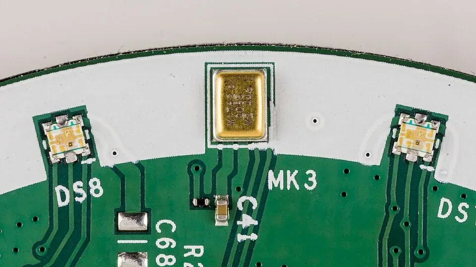
The practical drawing review starts at the enclosure opening and follows the path through mesh, seals and cavities to the microphone port. Check that no pad, solder, adhesive or coating obstructs the opening. Confirm the assembly process against the exact product’s handling and reflow instructions.
A top-port and a bottom-port device may require different PCB and sealing arrangements. Even a same-port replacement can interact differently with a gasket or cavity because of dimensional tolerances. Keep the mechanical stack-up in the qualification record rather than relying on a bare-board audio check.
For products with more than one microphone, evaluate relative channel response in the final geometry. Beamforming or noise-cancellation processing may be sensitive to mismatches that a single-channel level test does not expose.
Which sensitivity and overload limits should buyers compare?
Compare sensitivity only after aligning reference sound pressure, frequency, output units and operating mode. Then compare noise and overload behavior separately; a larger output level does not necessarily mean better usable performance.
Analog sensitivity expressed in dBV and digital sensitivity expressed in dBFS refer to different output scales. They cannot be ranked directly by comparing the printed negative numbers. Record the measurement definition from each datasheet, including any weighting and bandwidth used for noise figures.
For a hypothetical pair of microphones measured with the same reference and output convention, a 2 dB sensitivity difference corresponds to an amplitude ratio of 10^(2/20) ≈ 1.26. That is about 26% different amplitude under those assumptions. It says nothing about which microphone has the lower noise floor or more headroom before overload.
| Requirement | Evidence needed for the alternate |
|---|---|
| Quiet-sound capture | Noise specification and test bandwidth, plus assembled-system result |
| Loud-sound capture | Overload or distortion criterion at the relevant sound level |
| Frequency coverage | Response limits, low-frequency roll-off and acoustic-path evaluation |
| Production consistency | Sensitivity tolerance and channel-matching requirements |
Compare the incumbent and alternate with the same acoustic source, sound-pressure reference, geometry and capture settings. Save the raw captures before automatic gain or noise reduction changes their levels. Then evaluate the production processing separately. A level adjustment can align sensitivity, but it cannot recover clipping or improve the microphone’s original signal-to-noise ratio.
Use quiet input, normal speech or the intended signal, and the expected loud condition to check different limits. For an array, retain individual-channel results before evaluating the combined output. Repeat with the final seal and enclosure: a sensitivity shift that appears only after assembly calls for an acoustic-path investigation, not an automatic firmware-gain correction.
An RFQ can now specify the required interface and clocks, port and package drawing, sensitivity reference and tolerance, noise bandwidth and overload criterion. Attach the tested PCB, seal and firmware configuration to the component-alternative approval. If a lower quote depends on changing that acoustic stack, include the new assembly and qualification work in the comparison.
Frequently Asked Questions (FAQ)
Can software gain correct every microphone sensitivity mismatch?
No. Gain can adjust level, but it cannot restore signal lost to clipping or correct a different noise floor, frequency response or acoustic path. Confirm the physical and dynamic-range requirements as well.
Can a bottom-port microphone use the same land pattern as a top-port part?
Do not assume it can. Check the acoustic opening, PCB hole, pad layout, seal and enclosure path from the exact drawings. Similar external dimensions do not prove the sound path is compatible.
Does a digital output remove the need for acoustic testing?
No. A digital interface changes how data is delivered, not the microphone’s interaction with the enclosure. Test the assembled acoustic path and processing configuration against the application’s acceptance criteria.