Table of Contents
A 14-bit magnetic encoder divides one revolution into 16,384 codes, about 0.022° per step. At 3,000 rpm, the control loop can lose more than that to interface and filtering delay before the next output update.
That is why a standstill bench check can pass while the magnetic rotary encoder misses the motion loop’s deadline. Approve the sensor, magnet, mechanical stack and firmware as a combination, and keep the original assembly’s acceptance limits visible when comparing a replacement.
Does resolution predict angle accuracy?
Resolution predicts the size of the output step. Accuracy depends on the sensor’s specified error and the installed magnetic geometry, including centering, tilt, air gap and temperature.
The manufacturer-authored AS5048A/AS5048B datasheet describes 14-bit absolute angular output. Dividing a full revolution by the number of codes gives 360° ÷ 16,384 ≈ 0.022° per code. That calculation does not make a complete motor assembly accurate to 0.022°.
| Error source | How it enters the installed reading | How to verify |
|---|---|---|
| Sensor nonlinearity and noise | Specified error over temperature and supply | Datasheet limits at the application conditions |
| Magnet centering | Once-per-revolution error from eccentricity | Full-turn sweep against a reference |
| Tilt and air gap | Amplitude and harmonic error | Tolerance-corner tests at the permitted gap |
| Temperature | Magnet strength and mechanical shift | Soak tests at the operating extremes |
| Calibration | Residual offset and scale error | Before/after calibration comparison |
Set an allowable installed angle error, then allocate contributions from the sensor, magnet placement and calibration. Sweep the assembly through a full turn against a suitable reference. A measurement at zero and 180 degrees can miss periodic error from eccentricity.
Record both peak error and repeatability. A repeatable angle-dependent error might be corrected with a validated calibration table; changing error caused by bearing movement or temperature needs mechanical or sensing changes.
The interface and transaction sequence can block a replacement
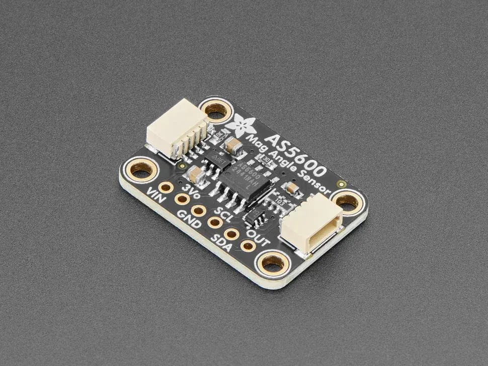
Check the complete protocol and timing, not just the serial-bus name. The AS5048A uses SPI while the AS5048B uses I2C; both offer PWM output. They are not interchangeable host connections merely because the family number is shared.
| Item | AS5048A | AS5048B | Replacement check |
|---|---|---|---|
| Host interface | SPI | I2C | Clock rate, frame length and bus voltage |
| Angle output | 14-bit absolute | 14-bit absolute | Scaling, signed format and wrap point |
| Additional output | PWM | PWM | Frequency, polarity and filtering |
| Package family | TSSOP-14 | TSSOP-14 | Land pattern and thermal/mechanical stress |
| Supply | 3.3 V or 5 V | 3.3 V or 5 V | Host logic level and unpowered-bus behavior |
The same datasheet describes SPI parity and error flags, and a read response associated with a previous command. Firmware that treats every received word as the angle requested in that same transaction can associate the wrong data with a control timestamp.
For incremental outputs, confirm how pulses and counts are defined, whether quadrature decoding is used, and when the index occurs. For absolute output, confirm whether the application needs one turn or multiple turns. A valid single-turn angle after restart cannot reconstruct an unknown number of rotations made while unpowered.
Magnetic and optical encoders also differ in ways that matter outside the datasheet. Magnetic sensing is generally more tolerant of dust and condensation; optical sensing can offer finer resolution but is more sensitive to contamination and mechanical alignment. Treat a cross-technology swap as a new design, not an alternate part number.
How much angle error does readout latency add?
At constant speed, the position lag is angular velocity multiplied by total measurement age. Include sensor conversion, filtering, bus transfer and scheduling before comparing candidates.
For a shaft speed of 3,000 rpm, angular velocity is 3,000 × 360 ÷ 60 = 18,000 degrees per second. A total data age of 100 microseconds corresponds to 1.8 degrees of motion. The 100-microsecond value is an example budget, not an AS5048 specification.
| Stage | Example budget | What to measure |
|---|---|---|
| Sensor conversion | 25 µs | Datasheet conversion time at the selected mode |
| Filtering | 30 µs | Group delay at the selected filter setting |
| Bus transfer | 20 µs | Clock rate, frame length and overhead |
| Host scheduling | 25 µs | Interrupt latency and task jitter |
| Total | 100 µs | End-to-end timestamp at the output |
This is why buying extra resolution can be less useful than reducing or compensating measurement delay. Timestamp the observation as closely as the hardware permits, quantify timing variation, and validate any prediction or phase compensation through the required acceleration range. A constant-speed correction may be inadequate during rapid acceleration.
Qualify the magnet and mounting with the electronics
Run a slow full-turn accuracy sweep and a dynamic test at the application’s relevant speeds. Repeat at the permitted mechanical tolerance extremes and operating temperatures. Exercise the assembly with nearby motors or current paths active, because the installed magnetic environment can differ from a bench setup.
Check field-strength diagnostics where provided. Reject an assembly that occasionally loses a valid angle even if its average error looks good. If an alternate fails only at a tolerance corner, changing the magnet or mounting may be more effective than adding software filtering.
Use the motor-driver current and decay-mode guide for the separate current-control behavior; an encoder change should not be used to mask a motor-drive problem. For a replacement, send the approved sensor suffix, magnet drawing, mechanical limits, host interface and angle-versus-speed requirement through a component-alternative request. Start from the ams-OSRAM brand page to confirm the package and interface suffix. Compare calibration and validation effort with the unit price: the lowest-priced sensor is not the lowest-cost replacement when new magnet tooling or a firmware rewrite is required.
Frequently Asked Questions (FAQ)
Does an absolute magnetic encoder retain the number of shaft turns after power loss?
A single-turn absolute sensor reports position within one revolution. Retaining multiple turns requires a separately specified mechanism, such as a powered turn counter or a true multiturn encoder.
Can a new encoder keep the existing zero-offset calibration?
Only after the assembly is checked. Sensor alignment, magnet position, output convention and stored-zero behavior can change. Re-establish the mechanical reference and verify the full rotation.
Does more output filtering always improve encoder performance?
Filtering can reduce apparent noise while increasing delay. Evaluate the filtered position against the control loop's motion and timing requirements, especially at high speed.
Is a magnetic encoder a drop-in replacement for an optical encoder?
No. Magnetic and optical encoders differ in resolution, contamination tolerance, mechanical tolerance and signal latency. Compare the installed accuracy, environment and control-loop timing before treating one as a substitute for the other.