Table of Contents
A replacement fan may spin on the bench and still fail the product: the controller may interpret its speed incorrectly, the supply may dip during simultaneous startup, or the installed airflow may be lower than the catalog comparison suggests.
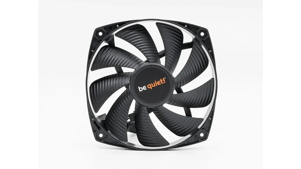
A four-wire pulse-width-modulated (PWM) fan has three interfaces to qualify: power, control and speed feedback. It also has to move enough air through the assembled enclosure. A replacement review needs both the electrical comparison and the installed thermal result.
Which electrical interfaces must match in a four-wire fan replacement?
Verify supply voltage, connector pin assignment, PWM input characteristics and tachometer output behavior separately. Four wires describe a common arrangement, but they do not establish universal signal levels, current limits or software interpretation.
Noctua’s PWM specification documents these interfaces for its specified fan families, including open-collector tachometer output and two cycles per revolution. The paper is a concrete example of the information to request; its limits should not be copied onto an unrelated manufacturer’s part.
Record the PWM frequency range, logic thresholds, allowed input voltage and behavior if control is absent. For the tachometer, check the output circuit, pull-up requirements, pulses per revolution and behavior when the rotor is stopped. Keep these in the interface comparison alongside the fan’s power supply requirements.
For a hypothetical fan producing two tachometer pulses per revolution, a measured 100 Hz signal represents:
100 × 60 ÷ 2 = 3,000 revolutions per minute.
If replacement firmware incorrectly assumes one pulse per revolution, it reports 6,000 RPM from the same signal. The fan can be physically working while the system’s diagnostic decision is wrong.
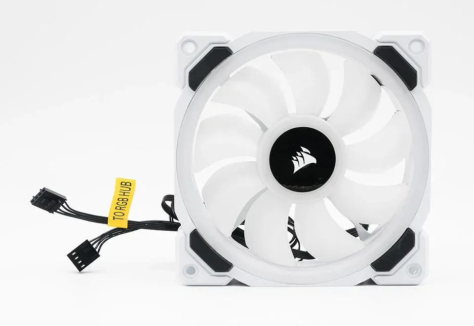
Some fans also carry separate lighting connectors. Identify each cable from the manufacturer’s drawing; an additional lighting lead does not change the motor-control interface into an interchangeable wiring scheme.
Why can a higher-CFM fan cool an enclosure less effectively?
Free-air flow is measured at little or no external flow resistance. Installed airflow depends on the intersection of the fan’s pressure-flow curve and the enclosure’s resistance curve, so comparing only maximum cubic feet per minute can select the wrong replacement.
SANYO DENKI explains this operating-point relationship in its fan-selection work. The practical consequence is to compare performance at the system’s resistance, not to combine maximum airflow and maximum static pressure as though they occur simultaneously.
Filters, vents, cable bundles, heatsink fins and mounting gaps all affect the installed result. A blocked intake can move the operating point; recirculation around a fan can reduce useful cooling without an obvious change in tachometer speed.
The acceptance measurement should reflect the product’s thermal objective: critical component temperatures at defined ambient temperature and workload, with the intended fan control enabled. Include the enclosure panels and filters that production units actually use. If the system has a dirty-filter requirement, evaluate that condition explicitly rather than assume the clean-filter result covers it.
A thermal-interface change introduces another variable. Keep the fan comparison separate from any gap-pad thickness or compression change so the test result can be attributed to a known configuration.
Startup and fault tests
Evaluate the fan from the actual power and control states the product can encounter, including simultaneous starts, low commanded speed and recovery from a fault. Define the product’s expected response before judging the replacement.
| Condition | Evidence to collect | Acceptance concern |
|---|---|---|
| Power application | Supply transient and startup current under the defined setup | Other circuits must not reset or lose regulation |
| Lowest intended command | Reliable start and stable running over specified conditions | A running fan may tolerate a duty cycle at which it cannot start |
| Missing speed feedback | Controller timeout and fault response | A cable or signal failure must not be mistaken for healthy cooling |
| Restart after interruption | Fan restart behavior and software recovery | Repeated automatic retries may interact with supply protection |
Test a start from rest at the lowest intended command separately from a ramp down to that command after the rotor is running. Log the supply transient, commanded duty and reported speed together. Then exercise loss of speed feedback and restoration of control through the controller’s specified fault procedure. The system should recognize the failure and recover as its requirements define, without a supply reset or a silent loss of cooling.
Include mounting orientation, cable routing, vibration, expected operating temperature and service access in the mechanical review. Confirm the meaning and conditions of any manufacturer lifetime metric rather than converting it into a guaranteed field-replacement interval.
Release the alternate only when the critical component temperatures meet the product limits at the stated ambient and workload, and its control and fault responses pass. If it needs a different minimum duty or timeout, treat that firmware change as part of the replacement; a purchasing swap alone will not deploy it.
Frequently Asked Questions (FAQ)
Can a matching four-pin connector guarantee the same pinout?
No. Verify the manufacturer’s connector drawing, signal assignment and viewing direction. Wire colors and mechanical mating alone are insufficient, especially across product families.
Does a zero-duty PWM command always stop a fan?
No. Minimum-duty and stop behavior depend on the exact fan implementation. Confirm the documented behavior and test restart from the intended stopped or minimum-speed condition.
Is a fan’s rated current enough to size the supply path?
Not by itself. Check startup, locked-rotor or restart behavior, the number of fans starting together and the supply’s protection limits under the intended conditions.