Table of Contents
A small load that glows, remains partly energized or fails to reset after an SSR input turns off may be responding to normal off-state leakage. Replacing the relay with another unit carrying the same headline current rating can reproduce the problem.
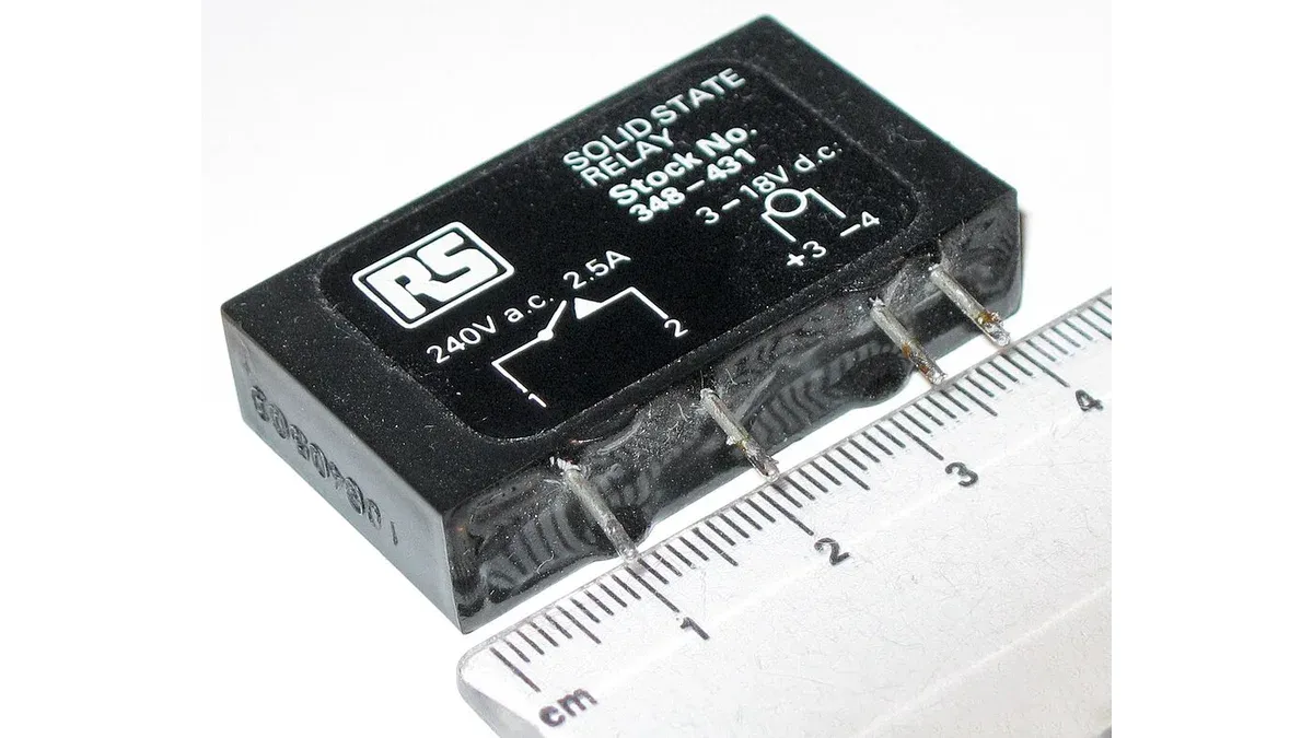
Solid-state relay (SSR) sourcing therefore starts with output topology and load behavior. Mechanical-relay habits do not transfer automatically: semiconductor outputs have leakage, voltage drop and thermal limits that must be matched to the circuit.
Why can an SSR leave a load energized when it is off?
The output can conduct a small leakage current even with no control input, and that current may exceed the load’s release threshold. Internal protection or snubber circuitry can contribute to this behavior; an off command does not mean the output behaves like an ideal open contact.
Omron’s leakage-current explanation describes how a load can fail to reset when SSR leakage is too large relative to the load’s release requirement. Compare the relay’s worst-case specified leakage at the relevant voltage and conditions with the actual load’s behavior.
Minimum on-state load is a separate issue. Omron’s minimum-load FAQ explains that triac and thyristor output devices need holding current. A load may therefore be too sensitive to off-state leakage and also too small for stable on-state operation.
For procurement, the useful record contains the load’s steady current, release behavior and any startup transient, plus the SSR’s leakage and minimum-load limits. If the load is an electronic input or LED assembly, obtain its relevant circuit requirements rather than treating it as a resistor with the same nominal wattage.
If the design needs a burden or bleeder network, include that network in engineering’s load and thermal review. Its value and power rating depend on the circuit; an added resistor changes the approved assembly and should not be left as an undocumented installation fix.
When should a buyer select zero-cross or random turn-on?
Select the switching behavior required by the load and control method. Zero-cross turn-on waits until AC voltage is near zero; random turn-on allows activation without that voltage-crossing delay and is used where the control scheme requires it.
Omron’s SSR terminology guide defines the zero-cross function in terms of load voltage. Keep that separate from the current-zero behavior involved in turning off triac or thyristor outputs.
A temperature controller using whole-cycle switching and a phase-control circuit do not ask the relay to do the same job. Transformers, motors and other inductive loads also require assessment of their own inrush and commutation conditions. “Zero cross” should not be translated into “best for every AC load.”
Record control voltage and input current as well. A replacement may satisfy the output requirement but demand an input drive that the existing controller cannot provide reliably over temperature and tolerance.
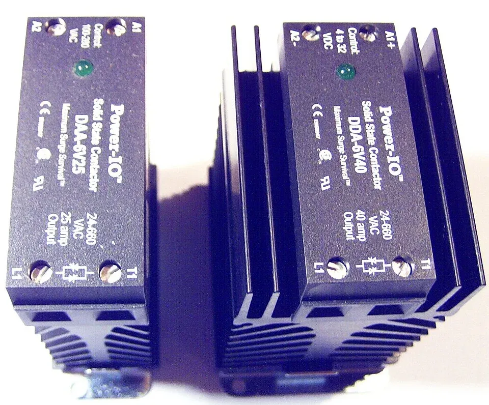
Thermal and load data for the replacement review
The replacement package should include the actual load waveform and the thermal conditions under which the relay must operate. A current rating detached from heatsink, ambient temperature and duty cycle is incomplete.
| Item | Comparison to make | Risk if omitted |
|---|---|---|
| Output structure | AC/DC suitability, voltage rating and turn-off behavior | A device can remain conducting in the wrong circuit |
| Load extremes | Minimum load, inrush, repetitive duty and transient conditions | Missed switching or excessive semiconductor stress |
| Loss and cooling | Manufacturer loss data, thermal resistance, heatsink and enclosure temperature | A nominally adequate current rating can overheat |
| Off state | Leakage versus the load’s release requirement | A commanded-off load may not reset |
| Input interface | Drive voltage/current and isolation specification | The control circuit may not switch the relay as intended |
Use the exact device’s loss data and derating curve with the intended heatsink, enclosure ambient and duty cycle. Triac on-state voltage drop and MOSFET resistance require different loss models. Include the specified mounting torque and thermal interface, then test the installation under the approved maximum-load and ambient conditions.
The release decision needs two separate results: the load switches and resets as required at its operating extremes, and the installation stays within the manufacturer’s thermal limits. A candidate that needs a larger heatsink than the enclosure can accommodate is not an acceptable substitution, even if its nominal current rating is higher.
Where the original design used contacts, compare the different constraints in the mechanical-relay replacement guide. Keep any revised load, drive or cooling requirement in the replacement specification. If one of those changes cannot be incorporated, retain the existing approved relay or evaluate another candidate.
Frequently Asked Questions (FAQ)
Can an AC-output SSR be assumed to switch DC?
No. Triac and thyristor output devices rely on AC current behavior for turn-off. Select a relay explicitly rated for the intended DC or AC load and operating conditions.
Does turning an SSR input off provide safe electrical isolation?
No. An SSR can pass leakage current and can fail in a conducting state. Use the application’s required isolation and protective measures; the control input is not a substitute for them.
Can a larger current rating eliminate the need for a heatsink check?
No. The rating depends on specified thermal conditions. Verify the loss model, ambient temperature, mounting and thermal path for the exact device and duty cycle.