Table of Contents
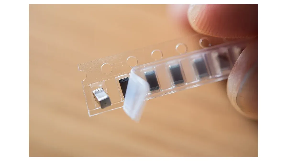
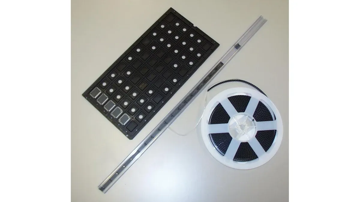
The device code can remain unchanged while the carrier arriving at the feeder differs. Pocket dimensions, tape width, pitch and pin-one orientation are assembly inputs that a component-only purchasing comparison can miss.
An approved tape-and-reel handoff connects the supplier’s actual carrier to the machine’s component library and placement rotation. It should make the first-piece check reproducible, especially after a supplier, carrier or packaging change.
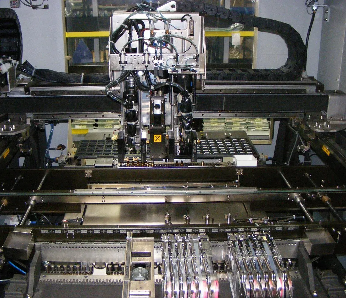
Pick-and-place machine photograph by Peripitus, CC BY-SA 3.0; resized for this page.
The exact part number does not establish orientation
A manufacturer can list more than one carrier configuration for a device. The assembly team must identify which supplied configuration applies instead of assuming that one remembered quadrant covers every reel.
For example, TI’s carrier lookup for TPD1E04U04DPYT, reviewed in November 2026, lists multiple carrier types, including Q1 and Q2 pin-one quadrants and different nominal pocket dimensions. This is an illustration of a carrier-control problem, not a claim that every TI device has multiple orientations.
A carrier drawing describes orientation relative to its stated reference view and feed direction. The placement program describes rotation relative to the board coordinate system. Those are different frames of reference and need an explicit mapping.
How should receiving hand the carrier over to assembly?
Preserve the full device and packing identity, identify the applicable carrier drawing, and pass the actual reel information to the feeder setup record. If the supplied carrier cannot be reconciled with the expected configuration, hold setup until the discrepancy is resolved.
The record should include tape width, pocket pitch, relevant pocket dimensions, reel size, pin-one orientation and the manufacturer’s view convention. Add the supplier lot, quantity and any respooling or splice history.
| Handoff field | Assembly use | Check before placement |
|---|---|---|
| Tape width and pitch | Feeder selection and indexing | Actual carrier matches setup |
| Pocket geometry | Pickup clearance and support | Component sits and releases correctly |
| Pin-one reference | Orientation mapping | Actual part marking and carrier view agree |
| Reel and leader condition | Loading and feed continuity | Feeder can load the supplied material |
| Lot/splice history | Traceability through the run | Changes remain associated with board output |
The cut-tape versus reel guide explains the purchasing form. This handoff addresses the narrower machine-orientation problem after that form has been chosen.
Which first-piece checks catch an orientation mismatch?
Verify the part’s physical orientation in the pocket, its orientation after pickup and the placed orientation against the board drawing. A correctly indexed feeder can still feed a component that the program rotates incorrectly.
Use the machine’s approved setup and inspection procedure. Confirm the relevant polarity or pin-one feature using the actual package marking, not a generic library thumbnail. If the marking is ambiguous, resolve it with the manufacturer package information before continuing the run.
After a carrier change, repeat the first-piece check even when the electrical MPN remains the same. Preserve the changed carrier reference and the accepted machine-library revision so the next operator does not inherit an unexplained rotation correction.
What should happen when rejects rise after a reel change?
Investigate carrier fit, indexing, pickup and orientation before increasing the attrition allowance. A sudden process change can indicate a setup or packaging mismatch rather than normal component consumption.
Separate empty-pocket events, pickup failures, vision rejects and orientation failures in the record. Compare the changed reel with the previous accepted carrier and inspect the actual feed path using the assembly team’s approved method. Do not alter the component library to force acceptance without understanding the difference.
The component attrition model can use the resulting measured loss after the cause is understood. The kitting quality guide keeps the carrier and lot information connected to the production kit.
A complete handoff finishes with the accepted carrier configuration, feeder setup and first-piece result attached to the job. That closes the gap between a commercially correct reel and a correctly oriented component on the board.
Frequently Asked Questions (FAQ)
Can two carrier variants for one device have different pin-one quadrants?
Yes. Manufacturer carrier tables can list multiple variants with different orientation information. Match the actual supplied carrier and its applicable drawing.
Does a sealed original reel remove the need for first-piece verification?
No. Original packaging supports identity and handling controls, but the feeder setup and placement rotation still need to match the supplied orientation.
Is a reel-diameter change necessarily an electrical part substitution?
No. It can be a carrier change, but feeder capacity, loading and traceability still need review. Keep the electrical and assembly change scopes separate.