Table of Contents
An eFuse is useful when a power rail needs more control than a one-time overcurrent element can provide. It can shape inrush, limit current, disconnect an abnormal load, report a fault, and either retry or remain off. Those functions only help when their thresholds and timing match the source, wiring, output capacitance, and load startup.
Selection therefore starts with fault conditions rather than a catalog current rating. A device that carries the normal load may still overheat while charging a large capacitor, nuisance-trip during a converter startup, or reconnect continuously into a hard short. The approval record should describe what happens before, during, and after each credible fault.
Start with the Faults the Rail Must Survive
Record the minimum and maximum source voltage at the eFuse pins, including regulation tolerance, hot-plug overshoot, cable drop, and any inductive transient. Add the load’s continuous current, startup profile, output capacitance, permitted voltage ramp, and maximum ambient or board temperature. These values define the operating envelope; a system label such as “48 V, 3 A” does not.
Toshiba’s August 20, 2026 announcement of the TCKE1401NM 80 V eFuse is a useful example of why the distinction matters. Toshiba positions the part for systems operating up to 54 V and lists 44.5 mΩ typical on-resistance, a 4 mm × 4 mm VQFN24D package, and multiple protection functions. Those values belong to that device and its stated conditions. They do not mean every 48 V rail can use it without a transient and thermal review.
Create a fault list that is specific enough to test:
| Condition | Required decision |
|---|---|
| Normal startup | Maximum acceptable ramp time and source droop |
| Output short before turn-on | Whether the eFuse may start, time out, or remain off |
| Short during operation | Peak current, disconnection time, and allowed rail disturbance |
| Input reverse connection | Whether the device, external network, or another element blocks it |
| Output held above input | Whether reverse current must be blocked |
| Repeated intermittent fault | Retry count, cooling interval, reporting, and service behavior |
Do not describe an overvoltage clamp or transient-voltage-suppression diode as interchangeable with an eFuse. The TVS selection process addresses fast transient clamping; an eFuse controls the power path over a different time and energy range.
Translate Load Behavior into Current Limit and Inrush Settings
Charging a capacitor requires current according to I = C × dV/dt. As an illustrative calculation, charging 1,000 µF at 1 V/ms requires 1 A before the downstream circuit draws its operating current. A current limit set just above the steady-state load can therefore extend startup or trip, even though the load is healthy.
Use the load waveform and tolerance limits rather than a single typical peak. Include converter soft-start, motor stall or acceleration, heater resistance when cold, and processors that enable several rails together. Then compare the eFuse’s current-limit range, threshold accuracy, blanking or deglitch behavior, and response to the desired ramp.
The TI introduction to eFuses separates inrush-current control from overcurrent protection and explains common protection functions. Apply those concepts using the exact candidate datasheet. Some devices regulate a programmed current; others offer a fixed threshold or different fast-trip and steady overload behavior.
A lower limit is not always safer. It may hold the internal switch in its linear region for longer while the output capacitor charges. The source may also collapse and restart, causing a repeated sequence that was absent from the nominal calculation.
Check Switch Loss and Safe Operating Area
During normal conduction, a first estimate of internal-switch loss is P = I² × RON. On-resistance normally rises with junction temperature, so a room-temperature typical value is not a worst-case thermal input. Use the maximum or characterized value at the applicable temperature when the datasheet provides it.
Startup and overload stress are different. The eFuse can simultaneously carry current and drop substantial voltage, placing its switch in a high-dissipation linear condition. Compare the voltage, current, duration, retry interval, package, and board thermal assumptions with the manufacturer’s safe-operating guidance. Thermal shutdown is a protective response, not a design target or proof that repeated stress preserves the intended lifetime.
When the application needs an external MOSFET sized for a larger linear-mode pulse or a live backplane insertion, use the separate hot-swap controller and MOSFET SOA workflow rather than treating an integrated eFuse as the same architecture.
Estimate the board’s temperature rise with the package and layout guidance, then measure it at the hardest operating point. Copper area, thermal vias, adjacent heat sources, airflow, and enclosure temperature can make two boards with the same part behave differently.
When reviewing candidates in the Toshiba, TI, or ST catalogs, keep the complete ordering code and package in the comparison. A family name cannot establish on-resistance, current-limit options, or thermal performance.
Choose Fault Recovery and Reverse-Blocking Behavior

Latch-off and auto-retry solve different operational problems. A latched device stops delivering energy until an enable transition, input cycle, or other defined reset. That behavior can be appropriate when a short needs inspection. Auto-retry can restore a load after a temporary event, but the retry interval and energy per attempt determine whether a permanent fault experiences a damaging thermal cycle.
For an unattended node, document how firmware learns of the event, what state the load enters, and which party may reset it. A fault flag or power-good output also needs valid voltage levels during partial power and startup; do not assume a status pin remains meaningful when its referenced supply is absent.
Reverse input protection and reverse-current blocking must be read as separate specifications. A single internal MOSFET has a body-diode path that may permit current in one condition even when the controlled channel is off. If the system must prevent an energized output capacitor or redundant supply from feeding the input, confirm the exact blocking direction and voltage range.
That is also the boundary between this page and an ideal-diode controller. An ideal-diode circuit prioritizes low forward loss, reverse-current response, and supply ORing. It does not necessarily provide the programmable overload protection or retry behavior expected from an eFuse.
Qualify the Exact eFuse on the Target Board
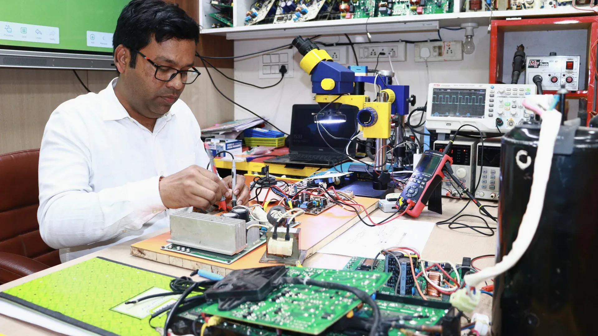
Bench tests should use the intended source impedance, cables, connectors, input protection, output capacitance, load firmware, and PCB layout. An ideal laboratory supply at the eFuse pins can hide cable inductance or source collapse that appears in the installed system.
Capture input voltage, output voltage, current, fault/status pins, and temperature for normal startup, maximum load, minimum and maximum input, output pre-bias, short before startup, short during operation, and repeated faults. Test both hot and cold conditions where load demand or switch resistance changes materially. If a compliance or safety requirement applies, add its defined abnormal tests and qualified review rather than inferring compliance from these engineering checks.
For alternate sourcing, compare threshold tolerances, timing, recovery mode, reverse behavior, package pinout, exposed-pad connection, enable logic, and qualification status. Preserve the test record with the approved code. The goal is not merely to find an electronic fuse that turns on; it is to control how much energy reaches the rail in every state the product is expected to survive.
Frequently Asked Questions (FAQ)
Can an eFuse IC replace a physical fuse?
An eFuse can add controlled inrush, current limiting, telemetry, and reusable fault handling, but it does not automatically satisfy the safety, isolation, or interrupt ratings assigned to a physical fuse. Keep any required protective device unless the equipment assessment approves its removal.
Should an unattended system use auto-retry or latch-off after an eFuse fault?
Choose from the system hazard and recovery plan. Auto-retry can restore a temporary load but may repeatedly heat a permanent short; latch-off prevents repeated energy delivery but requires a defined reset or service action.
Why can an eFuse shut down even when the normal load current is below its rating?
Startup charging, motor or converter peaks, current-limit tolerance, ambient temperature, input droop, and the device's safe operating area can trigger protection before steady state. Evaluate the complete startup waveform rather than only the nominal current.