Table of Contents
- Freeze the Port Role and Maximum Power Contract
- Choose a Standalone Controller, TCPC, or PD MCU
- Map PDO, PPS, AVS, and EPR Requirements
- Separate Negotiation From the Power Stage
- Cover CC, VCONN, Dead-Battery, and Protection States
- Plan Firmware Ownership and USB-IF Compliance
- Approve Alternates by Architecture and Configuration
USB-C Power Delivery selection begins with the port’s role and power contract. A sink-only product, a fixed-output source, a dual-role port, and a dock that exchanges data and power require different policy, power paths, protection, firmware, and compliance evidence.
The controller negotiates and supervises power; it does not make the connector, cable, DC/DC stage, battery charger, or thermal design disappear. Treat those blocks as one controlled configuration before comparing PD controller part numbers.
Freeze the Port Role and Maximum Power Contract

Define whether the port is a source, sink, or dual-role power (DRP) port; whether data roles can swap; whether the product supplies or consumes VCONN; and whether it supports only Standard Power Range (SPR) or also Extended Power Range (EPR). Record every intended source and sink power data object (PDO), current limit, voltage tolerance, and behavior when a preferred contract is unavailable.
USB-IF’s Power Delivery overview explains that USB PD works with the Type-C ecosystem and that EPR extended maximum power to 240 W. That figure is a system capability, not an IC rating. The cable, connector, source, sink, protection, and thermal path must all support the negotiated condition.
Also define behavior with legacy Type-C current, USB Battery Charging, non-PD chargers, electronically marked cables, and an invalid or damaged partner. A product that works with its development adapter can still fail interoperability if its fallback and error recovery were never specified.
Choose a Standalone Controller, TCPC, or PD MCU
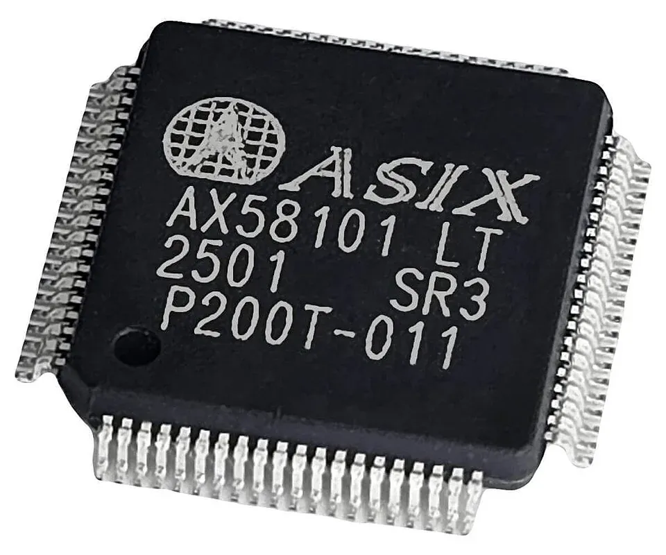
A standalone controller contains a policy engine and uses pins or nonvolatile configuration to implement a bounded source or sink behavior. It can reduce host software work for a fixed-function port. A Type-C Port Controller (TCPC) handles the physical and protocol interface under a host Type-C Port Manager (TCPM), giving system software more policy control. A PD MCU combines programmable processing with Type-C/PD functions and may manage the power stage or application logic.
Choose according to policy complexity, host availability during attach, boot timing, firmware-update responsibility, alternate modes, telemetry, field configuration, and compliance strategy. A host-managed solution creates a software dependency before safe power is established. A standalone solution reduces that dependency but can be less flexible when the product needs role swaps, several power profiles, or vendor-defined behavior.
TI’s USB-C PD controller portfolio, Microchip PD devices, and families from Infineon and ST span these architectures. Compare policy ownership before comparing package and current ratings.
Map PDO, PPS, AVS, and EPR Requirements
Fixed PDOs advertise specific voltage/current combinations. Programmable Power Supply (PPS) supports controlled voltage and current adjustment within advertised ranges. EPR adds higher-voltage operation and Adjustable Voltage Supply (AVS) behavior for applicable configurations. A controller must support the required protocol objects and the external power stage must safely produce or accept them.
USB-IF lists USB Power Delivery Specification Revision 3.2 Version 1.2, dated May 20, 2026, in its document library. Record the exact specification and compliance-test revision used by the project; “PD 3.x” is too broad for an approval record.
For a source, verify how PDOs are stored, how the controller selects a contract, and how it communicates requested voltage/current to the DC/DC stage. For a sink, confirm which PDOs it requests, fallback priority, input-voltage tolerance, and how the downstream system learns the available power. For DRP, define role preference, try states, swaps, and behavior during conflicting power sources.
Do not advertise an EPR contract that the cable or power stage cannot support. Confirm cable identity and current rating, connector rating, VBUS discharge, creepage/clearance at higher voltage, fault energy, and thermal limits. A PD message can request power faster than a slow protection or converter architecture can safely transition unless the complete sequence is designed.
Separate Negotiation From the Power Stage
Some PD controllers integrate power switches for defined voltage and current ranges. Others drive external path FETs or communicate with a buck, boost, buck-boost converter, charger, or adapter controller. Draw the source-to-load path and assign precharge, soft start, current sensing, reverse blocking, discharge, OVP, OCP, short-circuit, and thermal responsibilities.
Check how the controller measures or verifies VBUS before and after a contract. Threshold accuracy, ADC range, resistor tolerance, FET orientation, gate-drive voltage, discharge resistance, and converter settling determine whether the electrical rail follows the policy safely. If an external MCU programs the converter, define the safe default before firmware is running.
A battery charger IC regulates energy into a cell or pack. It does not necessarily negotiate the USB contract. If the charger and PD controller are separate, specify the interface that communicates input voltage/current limits and the response to renegotiation or source removal.
Cover CC, VCONN, Dead-Battery, and Protection States

Review attach and detach thresholds, CC orientation, Rp/Rd configuration, accessory states, cable marker communication, VCONN source capability, and dead-battery behavior. A sink that must charge a fully depleted product needs a valid state before the main MCU and its normal firmware are powered.
Map every partial-power case: controller off with VBUS present, host off with controller alive, source and sink supplies at different times, a live CC pin, and a connected cable during reset. Verify leakage and back-power paths. The safe state should not depend on an uninitialized GPIO.
Protection around the connector remains necessary. Evaluate electrostatic discharge, overvoltage on CC/SBU/USB data pins, VBUS surge, reverse current, cable short, thermal sensing, and contaminated or damaged connectors. Protection capacitance and placement must also fit the data rate when SuperSpeed or USB4 lanes share the receptacle.
The existing USB controller sourcing guide owns hub and host-controller decisions. A hub, retimer, redriver, protocol bridge, Type-C controller, and PD controller can coexist in a dock, but they are not interchangeable functions.
Plan Firmware Ownership and USB-IF Compliance
Determine whether policy is ROM-based, configured in one-time or rewritable NVM, loaded by a host, or implemented in application firmware. Record vendor tools, configuration binary, source files, compiler/tool versions, signing requirements, rollback behavior, field-update path, and recovery if an update is interrupted.
Compliance attaches to an implementation and configuration, not merely a silicon family. Verify the relevant USB-IF test ID or integrators-list evidence, reference schematic, firmware version, power profiles, connector, and advertised logo. A controller that appears on a certified reference design does not automatically certify a modified product.
Include interoperability testing with representative sources, sinks, cables, e-markers, role swaps, invalid profiles, detach/reconnect, brownouts, and firmware reset. Observe CC, VBUS, gate control, converter output, current, messages, and thermal behavior. Use the applicable USB-IF compliance test specification in addition to bench pairings.
Approve Alternates by Architecture and Configuration
Build the alternate matrix around PD revision, SPR/EPR, role support, PDO/PPS/AVS, integrated policy engine, TCPC interface, NVM, firmware ownership, power-path control, VCONN, dead-battery state, protection, package, and certified configuration. A source-only controller such as onsemi’s FUSB15101 illustrates how role and PPS support are explicit product properties, not generic capabilities of every PD IC.
Pin compatibility is secondary to state-machine and policy compatibility. A change can require new configuration tools, host drivers, converter commands, protection thresholds, compliance testing, and production programming. Control the orderable code and its programmed image as one item in the BOM.
For approval, archive the port requirements, power-path schematic, cable/connector ratings, firmware/configuration hash, PDO table, protection analysis, thermal results, interoperability log, and compliance evidence. That package lets procurement distinguish a true alternate from a controller that can exchange PD messages but cannot reproduce the product’s complete power behavior.
Frequently Asked Questions (FAQ)
What is the difference between a USB-C port controller and a USB PD controller?
A Type-C port controller can manage attach detection, orientation, and basic role behavior on the CC pins, while a USB Power Delivery controller also handles PD messaging and power-policy negotiation. Some ICs integrate both functions, so verify the state machine, policy engine, host interface, and supported PD revision.
Does a USB PD controller alone make a design support 240 W?
No. A 240 W design requires the applicable USB PD EPR capabilities plus a rated Type-C connector and cable, an appropriate source and sink power stage, VCONN and cable identification, protection, thermal design, firmware or policy configuration, and compliance testing.
Can one USB-C PD controller replace another without firmware changes?
Often not. Controllers can differ in architecture, policy ownership, nonvolatile configuration, host commands, power-stage control, protection, alternate-mode support, certified configurations, and boot behavior. Even pin-compatible devices require electrical, firmware, and compliance review.