Table of Contents
A ferrite bead selected from its impedance at 100 MHz may do little at the frequency causing a supply problem. It can also behave differently after the load current increases. Buying the same impedance label in another case size or series does not preserve the filter’s behavior.
For a component buyer supporting an EMI redesign, the useful request is a noise band, load-current range and allowable voltage disturbance. Those inputs let engineering compare the candidate in the circuit, instead of ranking nominal impedance alone.
What does a ferrite bead’s impedance rating leave out?
A single impedance value leaves out the frequency response, the balance of resistance and reactance, and the effects of DC bias. The relevant quantity is the bead’s behavior over the unwanted-noise band at the actual operating current.
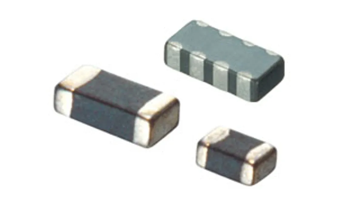
Murata’s chip-ferrite overview distinguishes product ranges by current capability and noise-frequency range. Those are separate selection dimensions. A high-current family should not be assumed to produce the same attenuation as a lower-current bead with a similar catalog impedance.
Request impedance curves, maximum DC resistance, rated-current conditions and available bias data for the exact candidate. The circuit’s load-step limit also matters: a bead that suppresses high-frequency noise can increase the impedance seen by a rapidly changing load.
Why can adding a ferrite bead increase supply noise?
A bead can be inductive at frequencies below its useful resistive region. Combined with a low-loss decoupling capacitor, it can form an underdamped network that amplifies a disturbance near resonance.
Analog Devices’ AN-1368 demonstrates resonance peaking, bias effects and several damping approaches. Its measured examples establish a mechanism; their numerical attenuation does not transfer automatically to another bead, capacitor or board.
For an illustrative local model, a bead represented by 0.5 µH and a 10 µF capacitor gives:
f₀ ≈ 1 / (2π√LC) ≈ 71 kHz
If the effective inductance becomes 0.1 µH, the corresponding estimate moves to about 159 kHz. These are hypothetical model values, not measurements of a named part. Real beads are lossy and frequency dependent, and real capacitors add bias-dependent capacitance and parasitics.
The calculation is useful for deciding where to investigate. It is not a substitute for measuring the network response.
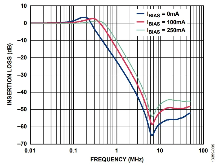
How should a candidate be tested under DC bias?
Test the complete filter at the lowest, typical and highest relevant load currents, while reproducing the source and load impedances that affect the response. Compare noise attenuation and load-transient behavior at the same operating points.
A practical sequence starts with the unmodified rail. Record the disturbance frequency, measurement location and probe setup. Add the candidate with the intended capacitor network, then check whether a new peak appears or the load-step droop becomes unacceptable.
Repeat at the temperature and supply conditions likely to change the result. A no-load noise improvement is insufficient if normal load shifts the impedance and restores the disturbance.
Keep a distinction between a single-rail bead and a common-mode choke. Their winding arrangements and current paths differ; an improvement measured with one does not qualify the other.
Choose damping from the failure mechanism
Possible changes include a deliberately lossy capacitor branch or another damping element supported by the design analysis. Each changes the network. A resistor in the wrong path can sacrifice DC voltage or high-frequency attenuation while apparently curing the original peak.
Use an acceptance table that makes the tradeoff visible:
| Requirement | Measurement to retain | Candidate decision |
|---|---|---|
| Noise reduction | Before/after spectrum at specified load | Meets the target over the relevant band |
| DC delivery | Rail drop at maximum load | Stays within the voltage budget |
| Transient delivery | Droop, overshoot and recovery | Does not disrupt the load |
| Thermal behavior | Bead temperature under operating current | Remains within the applicable limit |
| Stability of result | Response across bias and capacitor tolerance | Avoids a narrow successful corner |
The approved purchase line should identify the bead and the surrounding network revision. If an alternate requires a damping change, the procurement record should carry that dependency. A bead is being bought for its behavior in that network, not merely for the impedance printed in a catalog.
Frequently Asked Questions (FAQ)
Can a cable ferrite be substituted for a PCB power-rail bead?
They address different physical circuits and current paths. Select the component form and impedance behavior for the actual installation; a cable-suppression result does not qualify a PCB supply filter.
Does a bead's rated current guarantee its noise impedance at that current?
No. The current rating may be based on heating, while impedance changes with DC bias. Obtain biased impedance data or test the filter at its operating load.
Should every analog supply have a ferrite bead?
No. Add filtering to address an identified noise or coupling problem. An unnecessary bead can introduce voltage drop, transient impedance or resonance.