Table of Contents
A Hall-effect current sensor converts the magnetic field around a conductor into an electrical measurement. That allows DC and AC sensing without inserting a precision shunt into the signal path, and some packages provide galvanic isolation between the current conductor and low-voltage output. The same architecture makes mechanical position and surrounding fields part of the measurement system.
Choose the sensing structure before choosing the manufacturer or package. An integrated conductor, a magnetic-core assembly, and a field sensor mounted near an external busbar can carry similar current labels while presenting very different isolation, loss, bandwidth, footprint, and production-tolerance problems.
Choose the Architecture Before the Part Number

An integrated-conductor IC routes load current through a conductor inside the package and measures the resulting field. It offers a compact, repeatable current path, but its conductor resistance, thermal rise, isolation construction, and terminal current capability belong in the electrical review.
A core-based sensor concentrates flux around a conductor. It can achieve good immunity to external fields and measure high current, but the core adds volume, cost, air-gap tolerance, and possible magnetic nonlinearity. A coreless field sensor placed beside or above a busbar removes the core and can reduce insertion loss, yet its result depends more strongly on conductor geometry, placement, and neighboring phase currents.
| Architecture | Primary advantage | Main qualification risk |
|---|---|---|
| Integrated conductor | Compact and defined current path | Package heating and current-terminal limits |
| Core-based magnetic path | Flux concentration and external-field rejection | Core size, air gap, saturation, and assembly tolerance |
| Coreless external conductor | Low insertion loss and mechanical flexibility | Position, busbar shape, vibration, and magnetic crosstalk |
Allegro’s non-intrusive current-sensing discussion describes the use of magnetic sensing around conductors without a series shunt. Use the candidate’s own documentation to decide whether its architecture is characterized for the intended conductor and field arrangement.
Set Range from Peak Current and Fault Current
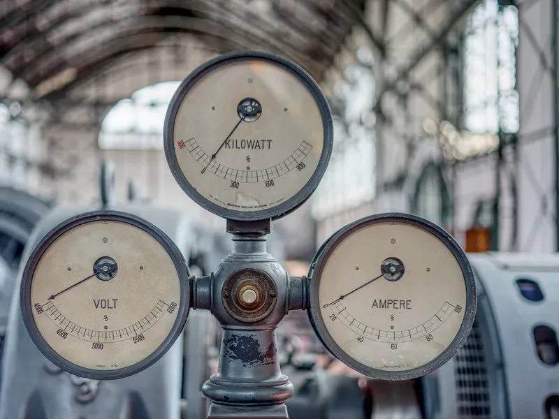
Define the continuous positive and negative current, normal peak duration, control-loop range, and fault current that may appear before another protection element acts. A sensor intended for bidirectional measurement also needs output headroom around its zero-current reference.
A high full-scale range prevents saturation but reduces signal per ampere at the ADC. A lower range improves resolution but can clip during acceleration, regenerative current, startup, or a fault. Reserve margin using the candidate’s guaranteed linear range and the actual analog-output limits, not only a nominal ampere label.
For an integrated-conductor device, estimate conduction loss and terminal heating at continuous and peak current. For an external-busbar sensor, verify the field stays within the sensor’s specified range across busbar tolerance and sensor position. Fault survival and accurate fault measurement are also different requirements: a sensor may survive a current that drives its output beyond the calibrated range.
Build a Temperature-Aware Error Budget

Start with offset at zero current, sensitivity or gain error, nonlinearity, noise, and their temperature drift. Then add application terms such as ADC reference tolerance, conductor or air-gap variation, board position, package rotation, ferromagnetic hardware, and fields from adjacent conductors.
Do not simply add every typical number or take the square root of unrelated maximum specifications. Classify each term as systematic, random, calibratable, temperature dependent, or unit-to-unit. Define the operating point at which the budget applies. Minimum-current accuracy is often dominated by offset, while full-scale accuracy is more sensitive to gain and field geometry.
TI’s August 25, 2026 TMCS2100-Q1 announcement illustrates a specific mechanical-error problem. TI states that its multiaxial coreless approach measures horizontal and vertical field components and reports less than 1% displacement error at 0.4 mm for the stated traction-inverter arrangement. Treat that as a claim about the named device and reference geometry, not a performance assumption for other Hall sensors or busbars.
If production calibration is planned, specify which errors it removes, the calibration temperature and current points, retained coefficient format, programming traceability, and recalibration trigger. Calibration cannot correct a later assembly shift that changes the magnetic geometry unless the system detects and models it.
Match Bandwidth and Delay to the Control Function
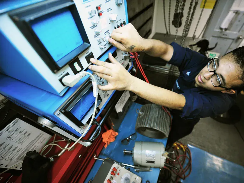
The required bandwidth depends on what consumes the measurement. Energy metering, slow overload protection, torque control, and fast short-circuit response have different signal and delay limits. A higher-bandwidth sensor also passes more noise to the ADC and may require filtering that adds its own delay.
Describe the current waveform, PWM frequency, harmonics of interest, maximum allowed phase lag, protection response time, and sampling strategy. Then check sensor bandwidth, propagation delay, step response, output drive, external filter recommendations, and the ADC’s acquisition behavior together.
For an inverter, neighboring phase edges can produce fast magnetic transients that do not represent the measured conductor’s current. Mechanical separation, differential or multiaxis techniques, filtering, and sampling position can all affect the result. Select the architecture with a model of those fields rather than assuming bandwidth alone separates signal from interference.
If a low-value shunt is acceptable and galvanic isolation is not required at the measurement point, compare the magnetic option with a current-sense amplifier error budget. The shunt path trades insertion loss for a measurement geometry that is usually less sensitive to conductor placement.
Validate Isolation and Mechanics Together
Where the Hall sensor provides an insulation barrier, document the system working voltage, transient conditions, insulation category, package creepage and clearance, environmental assumptions, and applicable certification evidence. A withstand-test value is not automatically the permitted continuous working voltage. The same distinction applies in digital-isolator selection.
Build test fixtures that represent the production busbar, fasteners, PCB stack, sensor height, neighboring phases, shield or enclosure, and expected tolerances. Test zero-current offset, positive and negative range, temperature, supply variation, bandwidth, overload recovery, and movement within the assembly tolerance. For vehicles or machinery, add vibration or position checks appropriate to the mechanical design.
Use the TI and Allegro catalogs to organize sourcing candidates, then approve the exact ordering code and magnetic arrangement. Preserve the conductor drawing, placement tolerances, calibration record, datasheet revision, and board-level results. A replacement is not qualified merely because it measures the same nominal current in a compatible package.
Frequently Asked Questions (FAQ)
Can a Hall-effect current sensor measure DC current?
Yes. Hall-effect sensing responds to the magnetic field produced by current and can measure DC as well as AC when the selected sensor and magnetic structure support the required range, offset stability, and bandwidth.
Does a Hall current sensor's isolation rating approve the complete system?
No. The component rating applies under its stated package, voltage, environmental, and certification conditions. PCB creepage, clearance, connectors, pollution assumptions, transients, and other barrier paths still require a system-level assessment.
Why can board-level Hall current accuracy be worse than the datasheet headline?
The assembled error can include offset, sensitivity, nonlinearity, temperature drift, conductor placement, air gap, adjacent magnetic fields, mounting tolerance, and ADC reference error. Combine the terms under actual operating conditions instead of using one typical specification.