Table of Contents
On a cold-start test, a board can report a stable 23.4°C while the object being controlled is closer to 40°C. The reading is precise, repeatable and wrong for the job because the sensor is measuring the board, not the surface the control loop cares about.
For a digital temperature sensor IC, define what must be measured first: local board temperature, enclosure air or a surface in contact with the package. Then allocate the error and response budget across the sensor, its installation and the host.
Accuracy and resolution answer different questions
Resolution is the smallest reported temperature increment. Accuracy describes how far the reading can be from the actual sensor temperature under specified conditions. Neither directly states the difference between the sensor and a remote object.
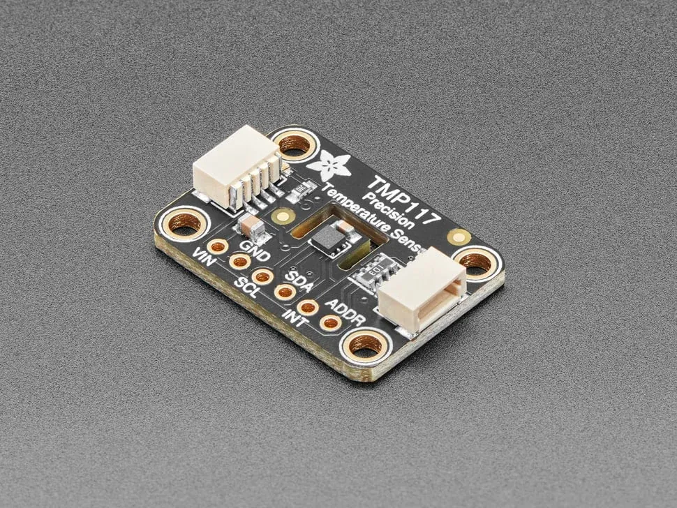
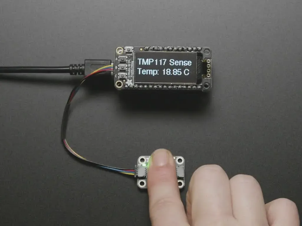
The TMP117 specification makes the distinction concrete: its 16-bit output has a step of about 0.0078°C, while the specified maximum error is ±0.1°C from −20°C to 50°C. Outside that interval, the permitted error increases. A “0.1°C sensor” label therefore describes a bounded operating window, not a universal accuracy claim.
For a hypothetical ±0.5°C system target, allocate 0.15°C to the sensor over the required operating interval, 0.20°C to the sensor-to-object gradient and 0.10°C to reference and calibration uncertainty. The arithmetic sum is 0.45°C, leaving 0.05°C of margin. These are example allocations, not measured performance. Dynamic lag needs a separate check because a static error budget does not capture a rapidly warming object.
If the installed gradient is 0.8°C, selecting a finer-resolution device will not rescue the budget. Placement or thermal coupling has to change.
Can TMP117 replace TMP102 without changing the board or firmware?
Not as a drop-in. Treat the change as a redesign review even though both devices provide I2C/SMBus temperature data.
| Item | TMP117 | TMP102 | What to check in the replacement |
|---|---|---|---|
| Output resolution | 16-bit, about 0.0078°C per step | 12-bit, 0.0625°C per step | Firmware scaling and rounding |
| Maximum error | ±0.1°C from −20°C to 50°C; wider limits outside | ±2°C from −25°C to 85°C; wider limits outside | The application’s real temperature interval |
| Interface | I2C/SMBus | I2C/SMBus | Address, bus voltage and pull-ups |
| Supply range | 1.8 V to 5.5 V | 1.4 V to 3.6 V | Host logic level and unpowered-bus behavior |
| Package family | WSON-6, 2 mm × 2 mm | SOT-563, 6-pin | Land pattern, thermal coupling and assembly |
| Register behavior | 16-bit format and pointer sequence | 12-bit format and pointer sequence | Signed format, reset defaults and alert setup |
The TMP102 product specification lists 0.0625°C output resolution and a maximum uncalibrated error of ±2°C from −25°C to 85°C, with a wider limit over its full range. Use the guaranteed maximum for the operating interval, not a typical value at room temperature.
The host test should include a known negative temperature and a known positive temperature, not only a room-temperature reading that happens to look plausible. Check alert release as well as assertion, and restart the host and sensor in different orders where the product permits it.
Why can a more accurate sensor respond too slowly?
The thermal path and digital measurement cycle both contribute delay. Package temperature has to approach the measured object, the conversion must complete, and the host must read and act on the result.
The TMP117 layout guidance discusses heat sources, thermal coupling and mechanical stress. Its exposed-pad guidance also shows why assembly rules must be device-specific: stronger board coupling can change both thermal response and stress-related error.
For a first-order thermal response, a time constant of five seconds gives roughly 95% of a temperature step after three time constants, or fifteen seconds. Real assemblies may have multiple thermal paths, so measure the response in the finished enclosure rather than assume this simple model fits.
Consider a control requirement to react within two seconds. If the chosen averaging configuration produces a new result once per second and the host polls once per second without synchronization, the digital portion can consume almost the entire budget before thermal lag is included. Reduce the conversion or polling interval, synchronize acquisition where possible, and retest with the actual filtering and alarm logic.
Qualification should reproduce the installation
Compare the reference temperature and sensor output after stabilization, then apply a repeatable temperature transition. Test with nearby electronics both idle and at the highest relevant dissipation. Repeat the assembly condition that matters in production, including enclosure, adhesive, airflow and board mounting.
A consistent offset may be correctable if the calibration process controls it. A gradient that changes with processor load or airflow needs a physical or model-based solution; a single stored offset will not cover it.
If the real task is measuring a remote probe, compare the wiring and error budget in the RTD interface guide before assuming an on-board digital sensor is the appropriate substitute. For an alternate sensor, start from the TI brand page and confirm the exact package, supply and ordering suffix. An industrial component request should carry the temperature interval, maximum allowed error and response requirement. If the installed gradient is larger than the sensor error, no alternate sensor will fix the budget; the mounting has to change.
Frequently Asked Questions (FAQ)
Does a 16-bit temperature result provide 16-bit measurement accuracy?
No. Resolution describes the output step. Maximum temperature error, thermal gradients, mechanical stress and measurement timing determine whether the installed reading is useful.
Can an I2C address match establish sensor interchangeability?
No. Compare register layout, numerical format, reset defaults, conversion control, alert behavior and bus electrical limits. Matching an address only means the host can address both devices.
Should every exposed temperature-sensor pad be soldered to ground?
Follow the exact device and package guidance. Thermal coupling and mechanical stress can affect precision differently; a generic exposed-pad rule can be unsuitable for a precision sensor.
What does the TMP117 ±0.1°C specification actually cover?
The ±0.1°C maximum error applies from −20°C to 50°C. The permitted error increases outside that interval, and the figure describes the sensor die, not the gradient to a remote object or the accuracy of the complete assembly.