Table of Contents
A vibration-monitoring purchase can fail even when the accelerometer has an attractive noise-density figure. The required frequency band may extend beyond its useful response, or a flexible mount may introduce a resonance inside the measurement band.
Define the fault information the system needs to observe before choosing the sensor. A bearing-monitoring task, a low-frequency imbalance measurement and a shock measurement may need different bandwidth, noise and range. The purchase specification should describe that measurement task and the installed sensor assembly.
Which bandwidth should a vibration-monitoring accelerometer cover?
It should cover the diagnostic frequencies the application needs, with specified response accuracy and adequate rejection outside that band. The motor’s rotational frequency is a starting point, but it may not include the harmonics or bearing-related signatures needed for diagnosis.
For a hypothetical machine rotating at 1,800 revolutions per minute, the rotational frequency is 1,800 ÷ 60 = 30 Hz. That does not establish a 30 Hz sensor-bandwidth requirement: the measurement plan may need higher harmonics, transients or other fault signatures.
Define the lowest and highest frequencies of interest, the allowable amplitude error and the required operating range before comparing parts. Distinguish a quoted −3 dB bandwidth from a tighter flat-response band. Also distinguish output data rate from useful sensor response.
Analog Devices’ vibration-sensing discussion explains why bandwidth and mechanical resonance matter to condition monitoring. A component’s maximum frequency specification is useful only with the response definition and measurement chain attached.
Sampling must also leave room for the anti-alias filter’s transition band. Frequencies above half the sample rate can fold into the measured band unless attenuated before the relevant sampling stage. ADI’s analysis of aliasing in digital MEMS accelerometers shows why the internal filtering and output rate both matter. For an analog sensor, include the external filter and converter. Filtering already-aliased data afterward cannot separate it from a real signal at the same in-band frequency.
How do noise density and bandwidth set the detection floor?
For approximately white noise, RMS noise is the noise density multiplied by the square root of the equivalent noise bandwidth. The result is an estimate of integrated sensor noise, not a guaranteed minimum detectable machine fault.
Assume a hypothetical constant noise density of 20 µg/√Hz and an equivalent noise bandwidth of 1,000 Hz. The estimate is:
20 × √1,000 ≈ 632 µg RMS, or 0.632 mg RMS.
Here, µg and mg denote fractions of gravitational acceleration. They are not mass units. If the equivalent noise bandwidth rises to 4,000 Hz under the same white-noise assumption, the estimate doubles to about 1.265 mg RMS; it does not increase fourfold.
The distinction between signal bandwidth and equivalent noise bandwidth is essential. For an ideal single-pole low-pass filter, equivalent noise bandwidth is π/2 times its −3 dB cutoff. Actual filters and sensor noise spectra may require integration of the measured or specified response instead of that simple approximation.
ADI’s ADXL1002 noise-performance note explains how a wide measurement bandwidth can include more noise than expected and why filtering matters. The illustrative 20 µg/√Hz calculation above is not an ADXL1002 specification or a bench result.
Why must mounting be included in the sensor purchase specification?
Mounting is part of the mechanical transfer path from the machine to the sensing element. Its stiffness, mass, contact and resonances can alter the amplitude and frequency response that reaches the sensor.
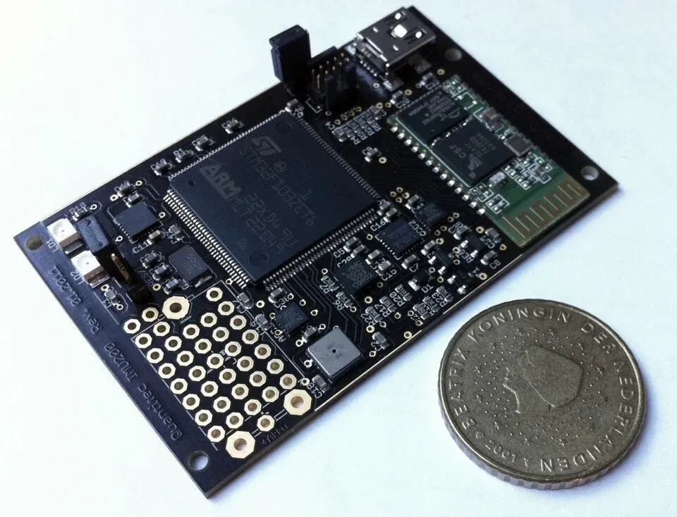
Specify the mounting method, surface preparation, orientation, enclosure and cable restraint appropriate to the application. A board held by a flexible fixture does not establish the response of the final bolted sensor housing. Likewise, a sensor tested in one mounting arrangement cannot be assumed to preserve its response in another.
During a comparison, hold the installation conditions constant or document their differences. Otherwise, procurement may attribute a mounting-induced peak to a superior sensor response, or reject a suitable sensor because its evaluation fixture attenuated the signal.
The assembled sensor also has an electrical boundary. A raw analog accelerometer, a digital MEMS board and an industrial sensor with a conditioned current-loop output are different deliverables. Define which one the purchase specification requires.
A purchase specification for the measurement chain
Require a documented measurement chain and an application-relevant comparison, including noise, response and overload behavior. Set acceptance criteria for the diagnostic task rather than copying a supplier’s best individual specification.
| Requirement | Evidence to retain |
|---|---|
| Frequency response | Response over the target band with the intended mounting |
| Noise | Spectrum or integrated noise under stated bandwidth and filtering |
| Peak range | Headroom for expected startup, impacts and vibration peaks |
| Sampling and filtering | Output rate, anti-alias provisions and filter configuration |
| Installation | Mounting drawing, axes, enclosure and environmental conditions |
| Repeatability | Test setup, calibration or reference method, and controlled revisions |
For a simple sinusoid, peak acceleration is √2 times RMS acceleration. Real machinery can have a larger crest factor, so size the range from the expected waveform and measured peaks rather than that sine-wave relationship alone. A shock-survival rating is also different from a linear measurement range.
Write the acceptance requirements in measurable terms: frequency limits and amplitude tolerance, integrated noise with its bandwidth, linear peak range, operating temperature and the installation drawing. Set the values from the diagnostic task; the illustrative noise calculation above does not supply an application acceptance threshold.
Compare the alternate with the reference measurement under the same mounting and excitation conditions, retaining the raw spectrum as well as any processed fault indicator. If a peak changes when the fixture changes, resolve the mechanical cause before changing the sensor selection. The industrial sourcing record should retain the accepted sensor, filter, firmware and mounting combination so later deliveries reproduce that measurement path.
Frequently Asked Questions (FAQ)
Does a high output data rate guarantee useful vibration bandwidth?
No. The sensor’s mechanical response, analog and digital filters, and mounting determine usable bandwidth. Output data rate describes sampling or reporting frequency, not a guaranteed flat measurement response.
Can software averaging recover a clipped vibration signal?
No. Once the sensor or signal chain clips, information is lost. Choose sufficient peak range and validate startup or impact conditions before relying on later digital processing.
Can a bare sensor IC be approved as equivalent to a complete industrial vibration sensor?
No. A complete sensor also includes mounting, enclosure, signal conditioning, power and an output interface. Compare the same product boundary and qualify the installed measurement chain.