Table of Contents
A replacement temperature probe labeled “10 kΩ NTC” may agree with the original at 25°C and disagree substantially elsewhere. The room-temperature resistance is one point on a nonlinear curve, not a complete sensor specification.
For a negative temperature coefficient (NTC) thermistor, qualify the resistance-temperature characteristic together with the readout circuit and probe construction. This guide concerns temperature sensing; it does not qualify the larger NTC devices used to limit power-supply inrush.
Why are two 10 kΩ NTC thermistors not necessarily interchangeable?
The two devices can share the same nominal resistance at 25°C while having different resistance-temperature curves, tolerances and thermal behavior. A replacement must fit the application’s complete temperature range and measurement model.
TDK’s NTC general technical information explains characteristic curves, resistance tolerances and thermal parameters. For procurement, the implication is to retain the characteristic identifier or resistance table as well as the nominal R25 value.
Beta is also incomplete without its definition. A B25/85 value is calculated over a different temperature interval from B25/50. Comparing those numbers as though they used the same endpoints can hide a curve difference.
Before changing the sensor, identify whether firmware uses a lookup table, a beta approximation or another fitted equation. The approved replacement record should reference the matching conversion data and firmware revision. A purchasing substitution that changes the curve may therefore require a controlled software change.
How much can different beta values change a reading?
Even a moderate beta difference can produce a substantial resistance difference away from the common reference temperature. A single-beta approximation illustrates the effect, but the exact manufacturer’s resistance table should govern a real comparison.
Consider two hypothetical 10 kΩ sensors at 25°C, with constant beta values of 3,435 K and 3,950 K. Using temperatures in kelvin:
R(T) = R25 × exp[B × (1/T − 1/298.15)]
At 50°C, or 323.15 K, the calculated resistances are approximately 4.10 kΩ and 3.59 kΩ, respectively. They agree at 25°C by construction, yet differ by about 0.51 kΩ at 50°C. A common room-temperature check would not expose that distinction.
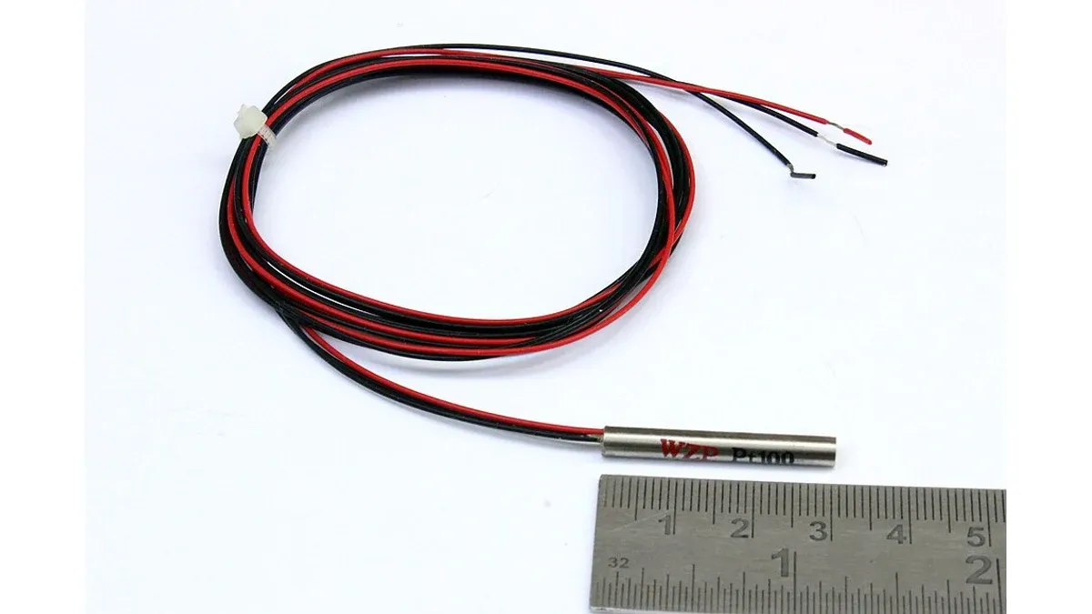
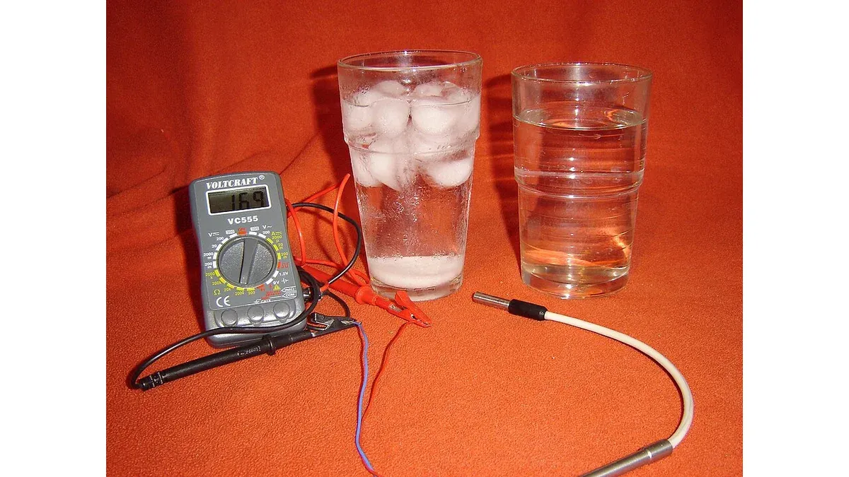
These are illustrative curves, not specifications for the probes pictured on this page. Real devices also have resistance tolerance, curve tolerance and limits on the accuracy of a single-beta model. For acceptance, calculate the resulting temperature error with the actual conversion algorithm instead of treating resistance percentage as an equal temperature percentage.
How can the divider bias heat an NTC sensor?
Current through the thermistor dissipates power in its sensing element, raising its temperature above the medium being measured. The resulting error depends on both electrical power and heat transfer in the installed environment.
For a hypothetical 3.3 V divider containing a 10 kΩ fixed resistor and an NTC that is currently 10 kΩ, the current is 3.3 V / 20 kΩ = 165 µA. The NTC dissipates approximately 0.272 mW.
If the installed dissipation factor were 1 mW/K, that power would correspond to an approximate steady-state rise of 0.272 K. The dissipation factor here is an assumed example, not a universal NTC value. Air, moving fluid, encapsulation and contact with the measured object can produce different heat-transfer conditions.
Lower bias or intermittent excitation may reduce heating, but introduces other constraints such as ADC settling and measurement timing. Check the complete circuit across the resistance range. The power at 25°C alone does not define every operating point.
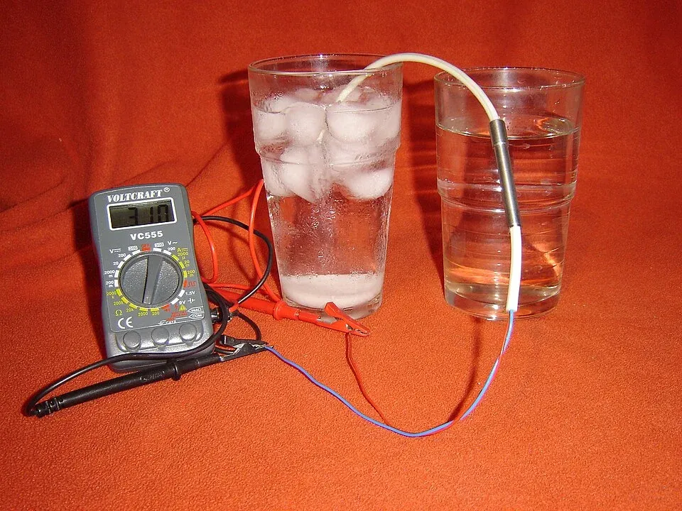
What evidence should qualify a replacement temperature probe?
Require the resistance characteristic, tolerances, operating range, thermal response and mechanical construction, then verify the assembled probe with the intended readout circuit. Neither connector fit nor one resistance measurement establishes interchangeability.
Compare several temperatures that cover the application, including the region where the control decision is most sensitive. Use a suitable reference and allow the sensor to reach the defined thermal state. Separate steady-state accuracy from response-time testing so that thermal lag is not mistaken for a curve error.
Retain the wiring and connector assignment, sheath dimensions, sealing requirements and mounting method. Those details matter when the purchase is a finished probe rather than a bare thermistor. State which conditions were tested and which remain supported only by documentation.
The RTD interface guide covers a different sensor system and its lead-wire errors. An NTC replacement needs its own nonlinear conversion and self-heating assessment even when it serves the same temperature-control function.
Frequently Asked Questions (FAQ)
Can a temperature-sensing NTC replace an inrush-limiting NTC?
Do not treat them as interchangeable. They serve different functions and require different electrical, thermal and mechanical specifications. Qualify the exact part for its intended use.
Does a connector-compatible probe preserve thermal response time?
Not necessarily. Probe sheath, encapsulation, mounting and surrounding medium affect response. Validate the complete probe assembly in its installed environment.
Can firmware calibration correct every NTC replacement error?
No. Calibration can address defined curve or offset differences within its model, but cannot automatically remove changing self-heating, thermal lag, poor contact or unsuitable environmental construction.