Table of Contents
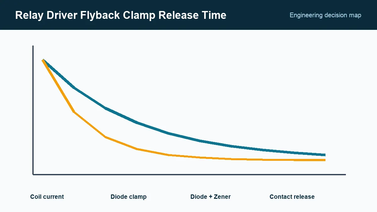
When a relay driver turns off, the coil current cannot stop instantly. The clamp sets the voltage that absorbs the magnetic energy and therefore sets how quickly current decays. A low clamp voltage is gentle on the transistor but can delay armature release; a higher clamp voltage releases faster but increases semiconductor stress.
This tradeoff matters when relay timing, contact life, or safe switching depends on a decisive release. The design must treat the coil circuit and contact circuit separately.
What coil energy and driver voltage should a relay clamp be rated for?
Rate the relay clamp for the magnetic energy present at turn-off and the peak driver voltage produced by the chosen suppression circuit. A first energy estimate is ½LI², using coil inductance L and turn-off current I; obtain manufacturer data or measure waveforms when inductance is not specified.
Create a voltage stack from the supply, clamp element, driver avalanche or drain/collector limit, and tolerances. Include transient overshoot caused by wiring inductance. Maintain margin to the driver’s absolute maximum and repetitive rating rather than relying on a one-time avalanche value.
How do you choose a relay clamp voltage for the required release time?
Choose a clamp voltage that lets the relay meet its release-time requirement while keeping the driver within its voltage and repetitive-energy ratings. A diode across a DC coil gives a low clamp voltage and slower decay; a diode-plus-Zener, TVS, or another higher-voltage network can shorten decay at the cost of increased voltage stress.
OMRON’s relay-coil suppression guidance, accessed September 24, 2026, notes that coil suppression can affect relay release characteristics. Use the relay manufacturer’s polarity and suppression recommendations, especially for models with internal diodes, LEDs, or operation indicators.
The required release time should come from the system. In a motor-reversing circuit, overlapping contact closure can be hazardous. In a communication signal, a few extra milliseconds may be harmless. Do not select the highest possible clamp voltage without a timing reason.
Driver and contact protection are different circuits
The flyback path handles coil energy on the control side. The contacts may switch a different inductive or capacitive load with much greater energy. That load needs its own suppression selected for AC or DC voltage, current, switching frequency, and allowed release behavior.
OMRON’s contact-protection FAQ, accessed September 24, 2026, describes how protection circuits are placed with respect to the load and contacts. Incorrect placement can suppress poorly or create leakage that keeps a load partially energized.

For AC contacts, a diode is unsuitable because it conducts on one half-cycle. RC snubbers and MOVs have different leakage, clamping, and aging behavior. Verify the load-side solution independently of the coil clamp.
Rate the clamp for repetitive operation
Calculate or measure pulse energy and multiply by the maximum operating rate to evaluate average heating. Check the TVS or Zener pulse curve at the actual pulse duration and temperature. A component that survives one pulse can overheat under rapid relay cycling.
Include diode reverse voltage, forward current, recovery behavior, and polarity errors. If the driver IC contains a clamp, confirm whether its rating is per channel, total package, single pulse, or repetitive. Multiple coils releasing together can exceed shared thermal limits.
PCB routing matters: place the loop so coil current commutates through the intended clamp without creating a large high-voltage loop near logic. If the relay is connected by cable, decide whether suppression belongs at the coil, the driver, or both based on current path and emissions.
Verify electrical current and mechanical release together
Capture coil current, driver voltage, and contact transition on the same time base. A contact-state signal or switched low-energy test path can reveal operate time, release time, and bounce without confusing them with load arcing.
Test minimum and maximum coil voltage, hot and cold coil resistance, rapid cycling, and the slowest permitted driver edge. The released contact must meet the application’s dead time before the next switching event.
Release records should state relay ordering code, coil voltage and resistance, measured or specified inductance, driver rating, clamp topology and tolerance, peak voltage, pulse energy, repetition rate, release-time limit, and separate contact-suppression method. That record prevents a “protective” diode substitution from quietly changing the relay’s mechanical timing.
Frequently Asked Questions (FAQ)
Why can a diode across a relay coil slow contact release?
The diode holds the coil voltage to a low clamp level, so magnetic current decays slowly. The armature remains energized longer and may traverse the contact gap more slowly.
How does a TVS or Zener clamp speed relay release?
A higher permitted clamp voltage creates a larger reverse voltage across the coil, increasing the rate at which current falls. The driver and clamp must be rated for the resulting voltage and repetitive energy.
Does the coil flyback clamp eliminate contact arcing?
No. The coil clamp protects the driver and changes armature release. Contact arcing comes from the switched load and may require a separate snubber, MOV, TVS, diode, or other load-specific suppression.