Table of Contents
- How do you select PPTC hold current at the actual operating temperature?
- How do you check whether a PPTC will trip before the load is damaged?
- Does a tripped PPTC fully disconnect the circuit?
- Budget resistance before and after a trip
- What conditions allow a PPTC to reset after a fault?
- Test nuisance-trip and protection boundaries
A polymer positive-temperature-coefficient device protects by heating into a high-resistance state. That thermal mechanism makes its behavior depend on ambient temperature, board heat, current history, fault amplitude, and cooling after the fault.
The selection problem has two sides: the device must carry every valid operating transient without nuisance trips, and it must limit each credible fault soon enough for the protected circuit and wiring.
How do you select PPTC hold current at the actual operating temperature?
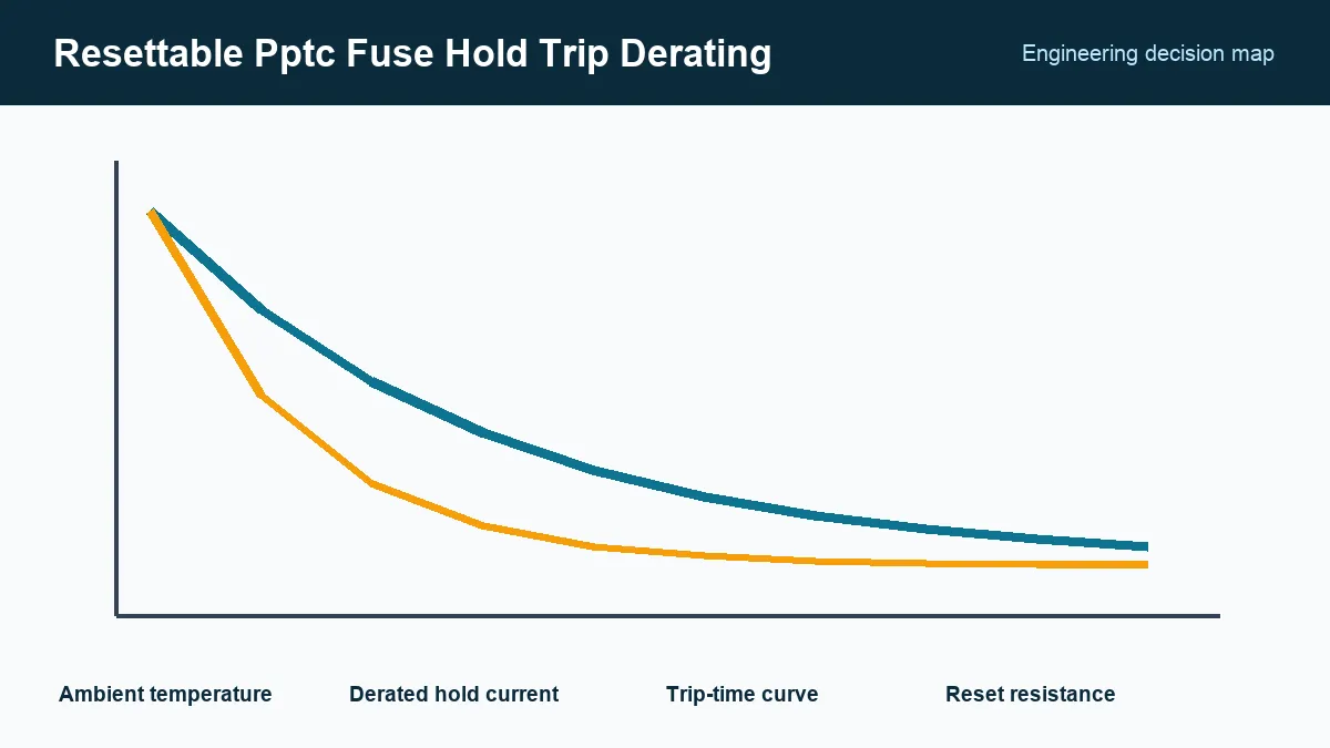
Select a PPTC whose temperature-derated hold current exceeds the maximum continuous load at the device’s local ambient, then separately check valid startup and inrush pulses. Use the candidate’s derating curve rather than its room-temperature rating, and include operating tolerance, repeated pulses, and nearby heat sources.
Local ambient can be higher than enclosure air because the PPTC sits near a regulator, battery, connector, or other heat source. Copper area and airflow change its heat loss. Test the production placement rather than assuming the 20–25 °C catalog condition.
How do you check whether a PPTC will trip before the load is damaged?
Compare the candidate’s worst-case time-to-trip at each credible fault current with the protected circuit’s permitted fault duration. Include the smallest overload available from a weak supply or long cable as well as a hard short; a low overload can persist much longer than a large fault.
Eaton’s PPTC application guidelines, accessed September 24, 2026, describes hold current, trip current, temperature derating, resistance, and time-current behavior. Use the device manufacturer’s current data for final qualification, particularly when distributor copies can lag a revision.
Compare trip time with connector, trace, cable, battery, and downstream semiconductor limits. A PPTC may protect against sustained overload while remaining too slow for a sensitive IC short.
Does a tripped PPTC fully disconnect the circuit?
No. A tripped PPTC enters a high-resistance state and still passes residual current, which can keep it hot. Its maximum device voltage and fault-current rating must cover the source, and the remaining current and power must be acceptable for the protected load.
Calculate whether that residual current is safe for the load and whether the source can maintain the tripped state. Some low-current supplies can settle at an intermediate operating point where the device repeatedly heats and cools.

For mains, high-energy batteries, or safety-critical interruption, determine whether an approved fuse or another protection architecture is required. A PPTC’s reset feature does not replace the breaking capacity and agency conditions of a fuse.
Budget resistance before and after a trip
Use maximum initial resistance to calculate normal voltage drop and heat, then review the specified post-trip resistance. The device can recover electrically only after power is removed or reduced enough to cool. Recovery time depends on package, ambient, airflow, and mounting.
Repeated trips, soldering, mechanical stress, and thermal aging can change resistance. If the PPTC is in a precision supply or communication line, include its resistance variation in the voltage and impedance budget.
What conditions allow a PPTC to reset after a fault?
A PPTC can reset only when current and residual power fall far enough for it to cool. Define the power-removal or reduction interval and the resistance or voltage-drop limit needed for restart, then test rapid retries and full cool-down in the production enclosure.
Where automatic restart is allowed, verify that repeated trip-and-recover cycles do not overheat wiring or the protected load. Where it is unsafe, the system needs a latched shutdown or service action beyond the PPTC.
Test nuisance-trip and protection boundaries
Run maximum normal load at hot ambient until thermal equilibrium. Apply repeated valid inrush profiles. Then test minimum and maximum faults at temperature, measuring current, voltage, trip time, surface temperature, and downstream stress.
After cooling, record resistance and verify normal startup. Repeat enough cycles to expose drift relevant to the application. Release records should state part number, local ambient range, derated hold current, load transients, minimum fault current, trip-time limit, maximum voltage and fault current, permitted leakage, reset condition, footprint, and agency requirement. That operating window supports a real alternate review instead of comparing one room-temperature current number.
Frequently Asked Questions (FAQ)
What is the difference between PPTC hold current and trip current?
Hold current is the current the device is specified to carry without tripping under stated conditions. Trip current is a test point at which it must transition within a defined time; neither value alone describes the full time-current curve.
Why must PPTC hold current be derated at high ambient temperature?
A PPTC trips through self-heating. A warmer environment requires less additional electrical heating to reach the transition, so the continuous current it can carry decreases.
Does a PPTC return to its original resistance immediately after a fault?
No. It must cool, and post-trip resistance can remain above the initial value for a specified period or longer. The circuit's available current and residual power affect reset.