Table of Contents
An RS-485 port is a circuit and a network, not just an eight-pin transceiver. Cable topology, termination, grounding, protection, controller timing, and node power states all affect whether the connection works reliably. Selecting the fastest available device can make some of those problems harder rather than improve the link.
Begin with a port specification that includes the actual network and environment. Use the transceiver’s ratings to narrow candidates, then qualify the complete interface on the intended hardware.
Specify Topology, Rate, and Direction Control
RS-485 defines an electrical interface; it does not supply the application protocol. A product using Modbus RTU, for example, still needs controller software and the appropriate protocol timing. A component description saying “RS-485” cannot establish that software compatibility.
TI’s RS-485 design guide explains bus configuration, termination, loading, and signal-integrity considerations. For a typical half-duplex linear bus, evaluate termination at the two physical ends and keep stubs short enough for the chosen edge rate and network. Select termination from the cable and interface design rather than installing a resistor at every node by habit.
Document the maximum required signaling rate, cable characteristics, expected length, node count, and connections. There is no single cable-length claim that proves performance for every rate and topology.
| Design field | Why it changes the transceiver review |
|---|---|
| Half or full duplex | Determines channel arrangement, wiring, and driver control |
| Data rate and edge rate | Affect timing, reflections, and emissions |
| Node loading | Contributes to the electrical load on the bus |
| Logic and bus supplies | Determine MCU compatibility and power architecture |
| Direction control | Governs when the driver releases a shared bus |
| Startup state | Determines whether a resetting node can disturb other traffic |
The controller’s driver-enable timing needs testing too. Releasing the bus too early can truncate a frame; holding it too long can interfere with another node’s response. A different transceiver delay can change the available margin even when the nominal data rate is unchanged.
Match Edge Rate to the Real Communication Requirement
A lower-speed, controlled-edge device may fit a modest-rate network better than a much faster part. Analog Devices’ RS-485 selection discussion explains the relationship between slew-rate limiting, emissions, and tolerance of imperfect interconnects. That does not eliminate the need for a correct network layout, but it is a reason to compare edge behavior alongside maximum rate.
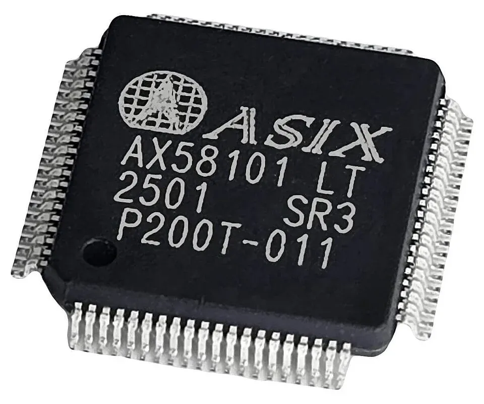
As a concrete screening example, TI specifies SN65HVD3082E as a nonisolated, half-duplex device optimized for signaling up to 200 kbps. A design requiring a higher rate cannot assume that an almost identical family name carries the same limit. Use the full ordering code and package-specific temperature information when preparing a sourcing request through the TI catalog.
Keep the validation record tied to the actual cable and loading configuration. Passing a bench test with a short cable does not establish performance for a long installed network with several powered and unpowered nodes.
Check Idle, Open, and Shorted Inputs Separately

“Fail-safe” should prompt a table lookup, not end the review. Determine the guaranteed receive output for an undriven terminated bus, an open input, and a short between the bus lines. Check the conditions under which the guarantee applies.
The Analog Devices discussion distinguishes those states and explains why a defined receiver threshold can prevent an indeterminate output when differential voltage is near zero. The system still needs to detect missing messages and other communication faults. A stable receive output is not evidence that a broken cable is transmitting valid data.
Assess external biasing across the whole network. Do not add a strong bias network at every node or remove existing bias solely because one replacement transceiver advertises fail-safe reception. Include the other installed devices, termination, loading, and required noise margin in the decision.
Also check what happens while the MCU resets. Define the required driver-enable default and verify it with the actual pull resistors and control pins. One node should not seize the shared bus before its software has initialized.
Separate Common-Mode Range, Isolation, and Surge Protection

The receiver’s common-mode operating range describes a condition for correct operation. Bus-fault or absolute-maximum ratings describe different limits. Neither is the same as galvanic isolation, and neither alone establishes port-level surge immunity.
For an isolated example, the ADM2483 datasheet describes a half-duplex transceiver with signal isolation and a 500-kbps data-rate limit. It uses separate logic-side and bus-side supplies; the isolation function does not generate the required isolated bus-side power.
The ADM2483BRWZ catalog page is therefore a candidate for a different architecture from the nonisolated SN65HVD3082E, not a replacement recommendation. If isolation is required, review the power path and the working-voltage, CMTI, and package criteria together. A component withstand rating does not certify the complete port.
For exposed industrial connections, define the applicable transient tests and the path taken by surge current. Use a coordinated TVS selection and clamping review rather than treating a component’s ESD headline as a system surge result.
Validate the Port and Preserve the Accepted Configuration
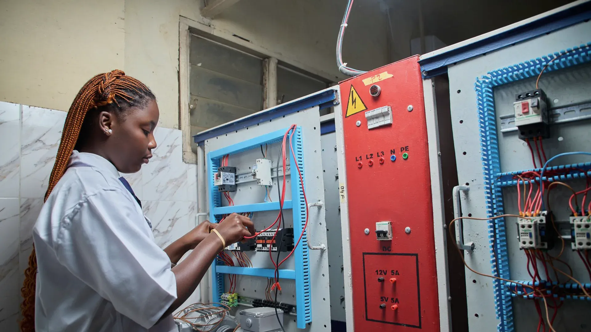
The broader industrial automation sourcing plan should assign responsibility for the complete interface. Procurement can collect candidate datasheets and traceability information, while engineering owns the network and protection assessment.
A practical test matrix includes normal traffic at the required rate, maximum intended loading, direction changes, node startup and shutdown, permitted connection disturbances, and recovery from communication faults. Environmental and immunity tests should follow the product’s applicable requirements and qualified procedures.
Record the transceiver ordering code, PCB revision, termination and bias values, protection components, software timing, and cable configuration used. If any of these changes, determine which tests must be repeated. This makes an RS-485 alternate review specific enough to support purchasing without assuming that every device with the same interface label behaves identically.
Frequently Asked Questions (FAQ)
Does an RS-485 transceiver implement Modbus?
No. The transceiver provides the electrical interface. A controller and software implement the selected communication protocol and its timing, framing, and error handling.
Does fail-safe reception guarantee communication on a broken cable?
No. Fail-safe behavior defines the receiver output under specified conditions such as an idle, open, or shorted input. It does not restore data transmission or replace application-level fault detection.
Does ADM2483 provide isolated power?
It integrates signal isolation with an RS-485 transceiver, but the bus side still needs its specified supply. Provide an appropriate isolated power arrangement when the system requires the power path to preserve the barrier.