Table of Contents
- How are thermocouple voltage and cold-junction temperature combined?
- Why can terminal temperature gradients defeat an accurate CJC sensor?
- How do you convert thermocouple voltage errors into temperature uncertainty?
- Protect the input without creating another junction problem
- Validate at temperature, not only in millivolts
A thermocouple produces a small voltage that represents a temperature difference. The measurement system must know the temperature where the thermocouple alloys meet copper, then combine that cold-junction temperature with the measured thermoelectric voltage using the correct thermocouple type.
The difficult errors usually come from thermal gradients and parasitic junctions, not ADC resolution alone. A useful design budget follows the signal from the connector to the reported temperature.
How are thermocouple voltage and cold-junction temperature combined?
Convert the measured cold-junction temperature to the equivalent reference-table voltage for the selected thermocouple type, add it with the correct polarity to the measured thermocouple voltage, then convert the total back to temperature. Compensation belongs in the thermoelectric-voltage domain because sensitivity varies with temperature.
Analog Devices’ cold-junction compensation guide, accessed September 24, 2026, explains why the reference junction is the point where thermocouple metal changes to the measurement system’s conductor. Identify that physical junction on the PCB rather than using the ADC’s location as a proxy.
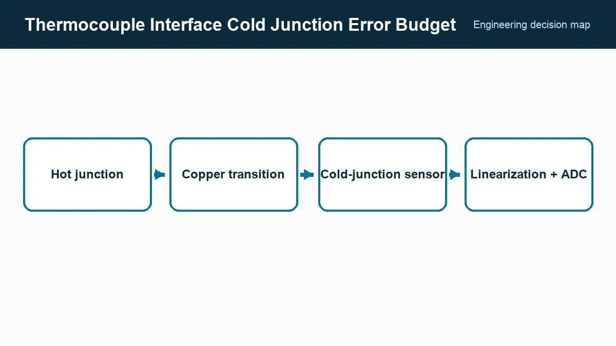
The cold-junction sensor’s accuracy is only one term. Its temperature must match both connector terminals closely. A precise sensor placed beside a warm regulator can report the wrong junction temperature with excellent repeatability.
Why can terminal temperature gradients defeat an accurate CJC sensor?
An accurate cold-junction compensation (CJC) sensor still gives the wrong correction if its temperature differs from the thermocouple-to-copper terminals. Keep both transitions close and isothermal, with a short thermal path to the sensor and separation from heat sources; accuracy at the sensor cannot compensate for an unmeasured terminal gradient.
Airflow, enclosure openings, cable conduction, screw-terminal mass, and repeated channel heating can create gradients. A connector mounted at the board edge may be cooled by ambient air while the sensor several centimeters inward follows PCB temperature.
Test the assembled enclosure during warm-up and steady operation. Add temperature sensors temporarily around the terminal block to map the gradient. Calibration in a uniform chamber cannot reveal an internal gradient created by normal product power.
How do you convert thermocouple voltage errors into temperature uncertainty?
Convert each input-referred voltage error using the thermocouple’s local Seebeck sensitivity at the temperature of interest; a small-error estimate is ΔT ≈ ΔV / S(T). Include offset and drift, bias-current error, gain error, ADC nonlinearity, noise, reference error, leakage, and interpolation, then keep cold-junction and thermal-gradient errors explicit in the total budget.
Texas Instruments’ thermocouple measurement reference design, accessed September 24, 2026, demonstrates a signal chain with input protection, precision conversion, and cold-junction measurement. Use its partitioning as a method, while retaining the limits of the components and range in the actual design.
Do not add every maximum linearly without stating why. Fixed errors that calibration removes, random noise, unit-to-unit limits, and temperature drift have different combination rules. Publish both uncalibrated and calibrated budgets if production calibration is part of the process.
Protect the input without creating another junction problem
Industrial thermocouple leads can carry common-mode voltage, ESD, and coupled noise. Protection resistors, capacitors, and clamps must tolerate those events while keeping leakage and thermally generated offsets within the budget.
Use matched input components and keep dissimilar-metal connections at the same temperature. Relay, multiplexer, and connector materials can introduce thermoelectric voltages. Input filtering should reject mains and switching interference without extending settling beyond the scan interval.
Open-thermocouple detection often injects a small current or relies on bias resistors. Calculate its normal error and recovery after a fault. If the interface is isolated, include leakage and common-mode limitations of the isolation barrier.
Validate at temperature, not only in millivolts
Test at several known temperatures across the specified range, with realistic cable and connector hardware. Include uniform ambient conditions to measure basic accuracy, then powered enclosure conditions to expose gradients. Reverse or exchange channels where possible to distinguish sensor error from board location.
Release records should name thermocouple type, wire and connector alloy, terminal construction, CJC sensor and placement, temperature range, input common-mode range, protection network, ADC configuration, reference, filter, linearization standard, calibration steps, and total error limits. That record makes a future ADC or connector substitution answerable without losing the thermal assumptions that made the original measurement accurate.
Frequently Asked Questions (FAQ)
Why does a thermocouple interface need cold-junction compensation?
The thermocouple voltage represents the temperature difference between the measuring junction and the copper transition at the instrument. Measuring that transition temperature lets the system refer the result to the standard tables.
Where should the cold-junction sensor be placed?
As close as practical to the thermocouple-to-copper junctions and in good thermal coupling with them. It should be shielded from regulators, processors, airflow, and other gradients that make its temperature differ from the terminals.
Can a copper trace be used between the connector and ADC?
Yes, after the thermocouple alloy transitions to copper at an isothermal junction. Additional dissimilar-metal junctions or unequal terminal temperatures create errors that must be controlled.