Table of Contents
A voltage mismatch does not identify a translator architecture. The same 1.8 V-to-3.3 V requirement can describe a push-pull SPI clock, an open-drain I²C bus, a direction-changing GPIO, or a signal that remains active while one rail is off. Each case needs a different control and power-state model.
Start with the bus behavior, then choose a device. Treating every translator as a group of voltage-compatible buffers can produce bus contention, slow edges, or back-powering that appears only during reset and shutdown.
How do you choose a level translator for push-pull or open-drain signals?
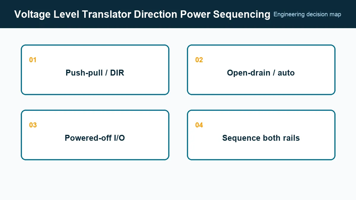
Choose the translator architecture from drive type and direction: fixed-direction push-pull lines, direction-controlled lines, and wired-AND open-drain buses have different requirements. Record source, receiver, toggle rate, idle state, pull-ups, loading, and possible unpowered endpoints for every signal before selecting a voltage-compatible device.
- A fixed-direction push-pull signal usually suits a unidirectional buffer powered from both domains.
- A known, changing direction can use a device with an explicit direction pin.
- An open-drain bus needs a translator intended for wired-AND operation and pull-ups on both sides.
- An auto-bidirectional translator must distinguish a real external driver from its own weak bias and one-shot circuitry.
Texas Instruments SCEA118, accessed September 24, 2026, organizes translator selection around interface type and direction rather than voltage alone. Preserve that interface classification in the schematic review so a purchasing alternate is compared against the same channel model.
Budget edges as well as propagation delay
A translator can meet its data-sheet frequency headline and still fail in a loaded system. For push-pull channels, compare propagation-delay limits, pulse-width distortion, output impedance, and rise/fall time at the actual capacitive load. For open-drain channels, the pull-up resistor and total bus capacitance set the passive rising edge.
Auto-bidirectional devices deserve an additional check. Their edge accelerators can interact with long traces, connectors, series resistors, or another translator. A strong external driver may be required to override an internal keeper, while a weak source may be misread as a direction change.
Build a timing budget from source clock-to-output, translator delay, board delay, receiver setup/hold, and jitter. Validate the minimum and maximum supply combinations because output drive and threshold timing change across the operating range.
What must a level translator do when one supply is off?
A level translator must tolerate the required pin voltages and provide the specified output state and leakage limit when either supply is absent. Verify those conditions in the exact data sheet; partial-power-down or input-tolerance features do not automatically cover every pin, rail sequence, or back-power path.
TI’s guide to common level-translation questions, accessed September 24, 2026, explains features such as Ioff and partial-power-down operation. Read the absolute-maximum and recommended-operating tables for the exact device: a tolerant input does not automatically guarantee high-impedance output behavior, and an overvoltage-tolerant pin is not necessarily safe with the device unpowered.
Test cold power-up, either rail first, either rail removed, reset assertion, and rapid cycling. Include pull-ups connected to rails that may remain present. Measure supply current as well as pin voltage; a seemingly valid logic state can hide damaging injection current.
Check control pins and default states
Direction and output-enable pins must have defined levels during controller reset. If they float, two push-pull endpoints can drive against one another. Use pull resistors referenced to a rail that exists at the required moment and ensure the control input itself tolerates the sequence.
Confirm that output enable produces the state expected by the bus. High impedance is different from driving low, and it may leave a receiver input floating. For I²C, disabling the translator can split the bus into two independently pulled-up segments; for SPI, it can release a chip-select or clock line that needs a stable idle level.
Qualify the full interface, not one channel on a bench
Use the production controller, receiver, trace length, connector, pull-ups, and expected cable if applicable. Exercise simultaneous switching and worst-case traffic. Observe both sides of the translator, including undershoot, overshoot, threshold crossing, delay, and direction turn-around.
The approved specification should state the architecture, channel count, voltage ranges, direction-control method, output-enable behavior, partial-power-down limits, maximum delay, loading condition, drive or open-drain capability, package, temperature range, and ESD requirement. Attach the power-state table and the measured timing margin. A substitute then has to reproduce the interface behavior, not merely fit the footprint and voltage labels.
Frequently Asked Questions (FAQ)
Can an auto-bidirectional level translator be used for SPI?
Only when its drive-detection method, channel loading, edge rate, and direction changes suit the specific SPI link. A direction-controlled translator is often easier to validate for push-pull clock and data signals.
What does partial-power-down protection mean?
It means the relevant I/O is specified to remain high impedance or otherwise tolerate a defined signal condition while a supply is absent. The allowed pin voltage and leakage must be checked in the datasheet.
Why can a level translator work at low speed but fail at the target rate?
Translator propagation delay, output drive, pull-up resistance, bus capacitance, edge accelerators, and transmission-line effects can consume the timing and voltage margin at higher data rates.