Table of Contents
A thermal gap pad with a higher conductivity can perform worse if it does not contact both surfaces or places excessive force on the board. A thicker pad can fill a gap while adding thermal resistance and changing the mechanical load.
A replacement decision therefore starts with the assembled gap and its tolerances. Compare the pad’s compression behavior and thermal performance at the installed condition, then retain the material, dimensions and assembly process on the purchase specification.
How do gap tolerances determine thermal pad thickness?
Calculate compression at both the smallest and largest assembled gaps, including pad-thickness tolerance. The selected material must maintain suitable contact without exceeding its permitted mechanical load across that range.
For a simple geometry, compression fraction is (uncompressed thickness − installed gap) / uncompressed thickness. In a hypothetical assembly with a 1.5 mm pad and a gap of 1.2 ± 0.2 mm, ignoring pad tolerance:
- At the largest 1.4 mm gap, compression is about 6.7%.
- At the nominal 1.2 mm gap, compression is 20%.
- At the smallest 1.0 mm gap, compression is about 33.3%.
If an example material were approved only for 10–30% compression, the nominal condition would pass while both tolerance extremes would fall outside that range. The 10–30% interval is an illustrative assumption, not a recommendation for any particular material.
Laird’s gap-filler guidance explains the role of conformable materials in bridging gaps between electronic components and heat-dissipating surfaces. For a specific purchase, obtain the material’s pressure-deflection information and suitable operating conditions. Percentage compression alone does not tell you the force applied to the package or board.
Is a higher conductivity pad always thermally better?
No. Bulk thermal conductivity is only one term; installed thickness, contact area, contact resistance and mechanical conformity affect the heat path. Compare the material at the thickness and pressure it will actually experience.
For a simplified, uniform slab, thermal resistance is Rθ = t / (k × A), where t is thickness, k is conductivity and A is heat-flow area. Consider two hypothetical pads across a 20 mm × 20 mm area:
| Installed thickness | Conductivity | Ideal bulk thermal resistance |
|---|---|---|
| 1 mm | 3 W/(m·K) | About 0.83 K/W |
| 2 mm | 6 W/(m·K) | About 0.83 K/W |
Doubling conductivity while doubling thickness gives the same ideal bulk result. At 10 W, either ideal slab would contribute about an 8.3 K temperature difference. This excludes both contact interfaces, heat spreading, temperature-dependent properties and the heatsink-to-ambient path; it is not a junction-temperature estimate.
Supplier thermal-impedance data at relevant thickness and pressure can be more useful than a catalog conductivity ranking. Check whether two test results use comparable methods and include the same interfaces before treating them as a direct performance comparison.
What mechanical and material details belong on the purchase line?
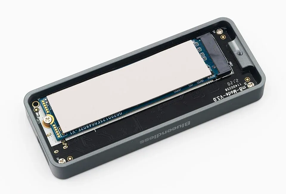
Specify the exact material, cut geometry, thickness tolerance, liner arrangement and any adhesive or reinforcement, together with the required assembly conditions. The line should preserve the approved construction rather than invite substitution by color and conductivity.
Add electrical insulation requirements where the interface must provide them. Check material compatibility with the application; silicone content, contamination sensitivity and environmental exposure may matter alongside heat transfer. These are design requirements to verify, not reasons to assume that every non-silicone or high-conductivity pad is superior.
Mechanical review should cover fastener position, board support, package loading and whether the pad spans components with different heights. A soft-looking sheet does not establish acceptable stress on every package underneath it. Preserve the pressure or compression assumptions used in the evaluation.
Validate the installed heat path before releasing the alternate
Compare candidates in the intended assembly at defined power, ambient conditions and mounting configuration. Use the same measurement locations and stabilization criteria so that the result reflects the interface change rather than a changed test setup.
Inspect contact and deformation using an appropriate method, and check repeatability across the relevant gap extremes. Include any rework rule: removing a heatsink can change pad condition and the next assembly’s interface.
If the heat source itself changes, revisit the full calculation. The MOSFET replacement guide explains why switching losses can change with an electrical alternate. A thermal pad approval based on the old dissipation should not silently cover the new power level.
Frequently Asked Questions (FAQ)
Can two thin thermal pads be stacked to replace one thicker pad?
Do not assume equivalence. Stacking adds an interface and can change contact, movement and compression behavior. Use an approved single construction or validate the proposed stack under the actual assembly conditions.
Does a thermal conductivity value establish electrical insulation?
No. Thermal and electrical properties are separate. Check the required dielectric behavior, thickness and test conditions for the exact material, including any assembly constraints.
Should a compressed thermal pad always be reused during rework?
Follow the material and assembly instructions. Prior compression, contamination, tearing or changed contact can affect reuse. Define the rework disposition instead of assuming the pad returns to its original condition.