Table of Contents
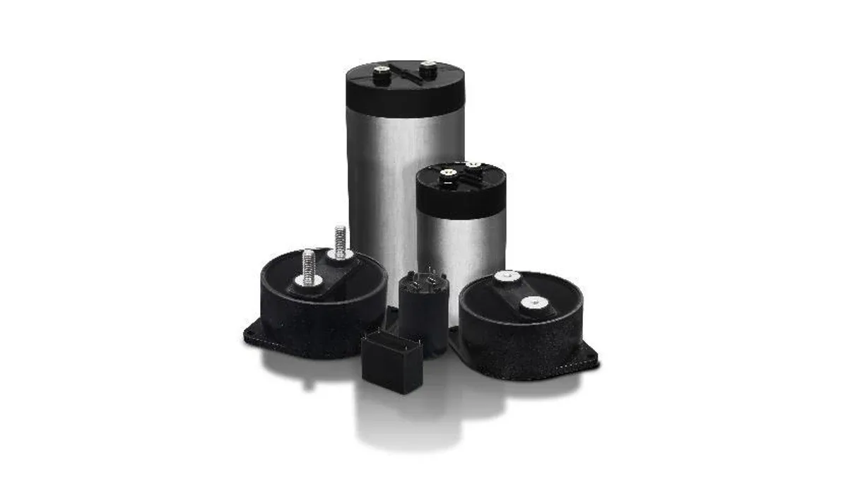
A DC-link capacitor quotation often emphasizes capacitance and voltage because those fields are easy to compare. In an inverter, the replacement also has to carry a time-varying current waveform through its film, internal connections and terminals without exceeding the installed thermal limits.
For film capacitor sourcing, separate stored-energy requirements from ripple heating and peak-current stress. A candidate can satisfy one of these checks while failing another.
How do ripple current and dV/dt limit a DC-link film capacitor?
RMS ripple current creates losses through the capacitor’s frequency-dependent resistance, while the rate of voltage change determines current through the relation i = C × dV/dt. Both must fit the exact part’s operating limits and installation conditions.
Cornell Dubilier’s DC-link capacitor application paper explains why the capacitor current depends on the source and inverter waveforms. Bus capacitance alone does not establish the current rating needed for an application.
For multiple significant frequency components, estimate loss using the RMS current and equivalent series resistance, or ESR, at each frequency. A single ESR value is a useful approximation only when its conditions represent the relevant waveform.
Separate the heating calculation from the pulse calculation
Consider a hypothetical 20 µF capacitor carrying 12 A RMS of ripple. If effective ESR at the relevant frequency and temperature is 3 mΩ, the simple loss estimate is:
P = I² × ESR = 12² × 0.003 = 0.432 W.
A candidate with 5 mΩ under equivalent conditions would dissipate approximately 0.720 W from that term. The extra 0.288 W matters only in relation to the actual heat path and allowed temperature rise; the arithmetic does not establish an acceptable hot-spot temperature.
Now suppose the same 20 µF capacitance experiences a voltage slope of 5 V/µs. The corresponding ideal capacitive current is:
i = 20 µF × 5 V/µs = 100 A.
That peak is not interchangeable with the 12 A RMS requirement. Duration, repetition and the manufacturer’s permitted pulse conditions still matter. These values illustrate separate checks and are not ratings for a listed product.
What belongs in a DC-link capacitor supplier comparison?
A useful supplier comparison retains the operating conditions behind each rating and identifies the evidence for any proposed equivalence. Ask for the exact code and current datasheet rather than comparing only series-level catalog values.
| Requirement | Evidence needed for the offered part |
|---|---|
| DC voltage and superimposed ripple | Permitted continuous and transient conditions at the required temperature |
| Capacitance and tolerance | Minimum useful value over the relevant conditions and service assumptions |
| RMS ripple | Frequency, ambient or case condition, and thermal installation behind the rating |
| Peak current and dV/dt | Applicable waveform, repetition and construction limits |
| Temperature | Allowed hot-spot or case limits and the method used to relate them to operation |
| Mechanical interface | Terminal geometry, dimensions, mounting and installation instructions |
Do not substitute an AC safety-capacitor classification for a DC-link operating specification. Different constructions may look similar while being intended for different duties.
Why can the same capacitor run hotter in a new installation?
Heat removal and parasitic electrical conditions depend on the installed arrangement. Busbar geometry, terminal connections, airflow, nearby heat sources and mounting can change the operating temperature even when the nominal electrical load is unchanged.
A replacement with different terminal spacing may require a busbar change. That change can alter current sharing or loop inductance, so the result is a system modification rather than a purely commercial substitution.
For a bank of capacitors, compare the distribution of current as well as the total. Check whether the hottest unit also experiences the highest current. An average bank temperature can hide a limiting component.
Define the approval around the actual bus
Retain the measured or modeled ripple waveform, voltage extremes, operating temperature range and installation drawing with the replacement assessment. Verify the candidate in the configuration covered by the approval.
The service-life model must also match the construction and manufacturer guidance. The assumptions used for aluminum electrolytic capacitor replacements should not be copied unchanged into a film-capacitor decision.
The purchase record should identify the exact approved code, document revision and installation restrictions. When a supplier offers another terminal option or package size, reopen the affected electrical and thermal checks instead of treating the common capacitance value as sufficient equivalence.
Frequently Asked Questions (FAQ)
Can parallel capacitors be assumed to share ripple current equally?
No. Differences in impedance, connection inductance and temperature can produce unequal sharing. Evaluate the bank and bus layout rather than dividing total current by the part count.
Does self-healing make every overload harmless?
No. Self-healing is a construction property with finite operating limits. It does not remove voltage, temperature, current or end-of-life restrictions.
Should a replacement use the same mounting torque?
Use the exact manufacturer's installation instructions for the offered construction. Terminal and mounting requirements can change between superficially similar parts.