Table of Contents
Two terminal blocks may both be described as “three-way, 5 mm, 16 A” while accepting different conductors and requiring different installation conditions. An alternate can fit an empty board yet become unusable once the enclosure, wire ferrules and screwdriver are present.
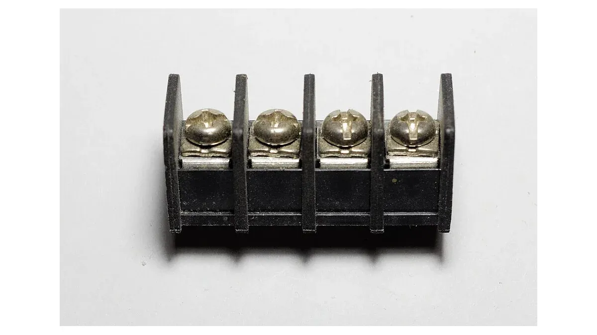
Treat the printed circuit board (PCB) terminal block as a board-to-wire system. Purchasing needs a mechanical comparison, a conductor-preparation specification and the electrical rating conditions. A photo of a green housing does not establish any of those fields.
Can a 5.0 mm terminal block replace a 5.08 mm part?
Not on pitch alone. The mismatch accumulates across the row, so the full pin pattern and tolerances must fit the actual board without forcing the terminals.
For a hypothetical ten-position row, there are nine pitch intervals. The difference between 5.00 mm and 5.08 mm produces 9 × 0.08 mm = 0.72 mm of end-to-end span mismatch. Aligning one end transfers that mismatch to the other; centering the part distributes it but does not eliminate it.
The board-hole pattern, pin dimensions and positional tolerances determine the available fit margin. Lead bending should not be used to turn a mismatched drawing into an approved footprint unless the manufacturer and design explicitly allow that assembly method.
Check height, wire-entry direction, pin length and mounting orientation as well. In a pluggable system, the board header and removable plug form a mating pair: matching the screw-terminal pitch does not establish compatibility between different manufacturers’ interfaces.
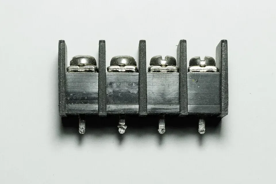
Which wire range applies when ferrules are used?
Use the range specified for the actual conductor preparation, including whether a ferrule has an insulating collar. A bare stranded-wire range does not automatically apply to a ferruled conductor of the same nominal cross-section.
The Phoenix Contact PCB terminal-block catalog lists separate connection capacities for rigid, flexible and ferruled conductors, along with stripping length and connection instructions. That separation matters when comparing alternatives: a field-wiring practice must remain compatible with the proposed terminal.
Build the receiving and assembly instruction around the actual wire rather than a broad AWG range:
| Installation detail | What the alternate record should identify |
|---|---|
| Conductor | Solid or stranded construction and cross-section |
| Preparation | Bare wire or exact ferrule style and dimensions |
| Exposed length | Required strip length and insertion depth |
| Clamping method | Screw, spring or push-in procedure |
| Tooling | Required driver access, release tool or torque instruction |
If the contract manufacturer already uses a standard ferrule, verify that combination instead of changing the terminal and leaving the wire-preparation drawing untouched. Excess exposed conductor and incomplete insertion are assembly problems that a nominal current rating cannot resolve.
Why can one terminal block have several current or voltage ratings?
Ratings depend on the assessment conditions and applicable approval system, including conductor size and insulation conditions. Compare candidates under the same intended use and documented scope rather than selecting the largest value shown on each page.
A manufacturer’s technical table can distinguish voltage by installation conditions such as pollution degree and overvoltage category. Approval-specific values may also differ from a general catalog value. Obtain the current documentation for the exact ordering code when the finished product relies on a particular component approval.
Do not claim that replacing one recognized component with another automatically preserves the equipment’s approval. The product-level assessment may depend on how the component is used. Procurement’s job is to provide the exact evidence and flag the change for the existing design-control process.
How should an alternate be checked in the assembled product?
Check the terminal with the real board, enclosure, wire preparation and installation tools, then assess electrical and mechanical performance under the defined application conditions. A bare-board fit check is only the beginning.
Confirm that an installer can reach the screw or release feature, insert the specified conductor fully and route the wire without an unsupported bend or interference. Check access again with neighboring positions populated. Retain the resulting drawing and assembly-instruction changes with the alternate approval.
The broader connector qualification workflow covers contact-system durability and environment. For a terminal block, add the conductor and installation conditions explicitly so that an approved sample can be reproduced on the production line and in the field.
Frequently Asked Questions (FAQ)
Can two wires be placed in one terminal because their combined area fits?
Only if the exact terminal documentation permits that conductor arrangement. Check the allowed number, type and cross-section of conductors and the specified preparation method.
Does a component flammability classification certify the complete product?
No. A material or component classification applies within its documented scope. It does not establish the compliance or safety of the assembled equipment.
Can tightening torque be copied from a similar-looking terminal?
No. Use the torque instruction for the exact terminal and fastener system. Similar body size does not establish the same clamping force or mechanical limit.