Table of Contents
A higher farad rating is not enough to approve a supercapacitor replacement for a controller backup rail. The load may reach its undervoltage limit before the stored energy is useful, particularly when series cells, ESR and the power converter are overlooked.
Start with the required backup interval and the circuit’s permitted voltage range. Then compare the proposed storage assembly at the operating and end-of-life conditions. The following example is a sizing calculation with explicit assumptions, not a claim about a particular product’s measured runtime.
How do series-connected supercapacitors change usable capacitance?
Equal cells in series provide the capacitance of one cell divided by the number of cells, while their ESR values add. The stack can support a higher total voltage only if each cell remains within its individual limits.
Two hypothetical 10 F cells in series therefore form a 5 F stack. If each has 0.10 Ω equivalent series resistance (ESR), the total is 0.20 Ω before adding interconnect resistance. Listing the assembly as “20 F” by adding the two labels would produce a serious sizing error.
Eaton’s supercapacitor application guide discusses series arrangements, leakage and balancing. Its application guidance is a reason to evaluate individual cell voltage, not permission to operate every stack at the sum of its nameplate limits.
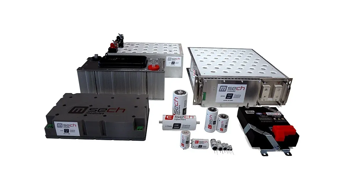
Cell tolerances and leakage differences can produce unequal voltages. The replacement review must therefore include the balancing circuit and its behavior during charging, standby and discharge. A module with integrated balancing and two loose cells are different procurement items even when their nominal stack capacitance matches.
How long can a supercapacitor support a constant-current load?
For an ideal constant-current discharge, hold-up time is capacitance multiplied by the usable capacitor-voltage change, divided by current. Deduct the initial ESR drop and evaluate the load’s cutoff voltage at the actual output node.
Use this hypothetical set of assumptions:
| Input | Assumed value |
|---|---|
| Effective stack capacitance | 5 F |
| Initial capacitor voltage | 5.0 V |
| Constant load current | 0.20 A |
| Total series resistance | 0.20 Ω |
| Minimum load voltage | 3.0 V |
The immediate resistance drop is 0.20 A × 0.20 Ω = 0.04 V. With constant capacitance and resistance, the estimated interval becomes:
t = 5 F × (5.0 V − 0.04 V − 3.0 V) / 0.20 A = 49 s
This is an idealized result. It omits capacitance tolerance, aging, temperature effects, leakage, balancing current and other losses. Those terms reduce or otherwise change the available margin and need their own inputs.
A regulated constant-power load is different because input current rises as voltage falls. Do not reuse the 49-second answer for that case. A converter-backed design needs an energy and efficiency calculation over its input range, followed by application validation.
Why do leakage and balancing affect replacement approval?
Leakage and balancing currents consume stored charge, and differences between cells affect voltage sharing. They can dominate a low-power standby requirement even when the discharge load is modest.
Compare leakage under the manufacturer’s stated voltage, temperature and conditioning time. A value observed immediately after charging is not necessarily comparable with a specified stabilized value. The Eaton application guidelines provide the relevant context for interpreting these conditions.
For passive balancing, include resistor current in the standby budget. For active balancing, check its operating range and consumption rather than assuming it is lossless. The purchase comparison should make clear whether the quoted item includes the balancing function or requires additional circuitry.
What should be compared on a supercapacitor quote?
Compare usable backup capability, charging requirements and physical integration for the exact cell or module. Nominal capacitance, voltage and price are only the initial screening fields.
Retain the capacitance tolerance, ESR method, leakage conditions, permitted temperature and voltage exposure, and any end-of-life criteria used in the sizing model. Add dimensions, polarity, terminals and mechanical support. If the offered module changes the number of series cells, rebuild the voltage-sharing and charging analysis.
The acceptance check should reproduce the product’s charging state and actual discharge load, including its cutoff behavior. Record the initial conditions and endpoint so that later samples can be compared consistently. For capacitors serving primarily as ripple filters, the separate electrolytic replacement guide addresses a different task; a ripple-current comparison cannot establish backup duration.
Frequently Asked Questions (FAQ)
Can a larger-capacitance supercapacitor overload the charging circuit?
It can change the charge duration and energy demand. Check current limiting, startup behavior and the allowed recovery time before increasing capacitance, even when the backup interval improves.
Does a low initial ESR guarantee adequate backup after aging?
No. Evaluate the allowed capacitance loss and ESR increase over the intended temperature and voltage exposure. Initial measurements establish only the starting condition.
Can a supercapacitor directly replace a rechargeable battery?
Not without a system assessment. The voltage-discharge profile, stored energy, leakage, charging circuit and converter operating range differ. Equal physical size does not establish equivalent backup behavior.