Table of Contents
“SMA male” is an incomplete purchase description when a cable assembly may use reverse-polarity SMA. Threaded bodies can appear compatible while their center contacts cannot form the required connection.
A reliable RF connector order separates mating identity from electrical performance. First establish which two interfaces must mate. Then define the transmission path, cable or board termination, installation envelope and acceptance evidence. That sequence prevents a mechanically plausible substitute from becoming an undocumented RF change.
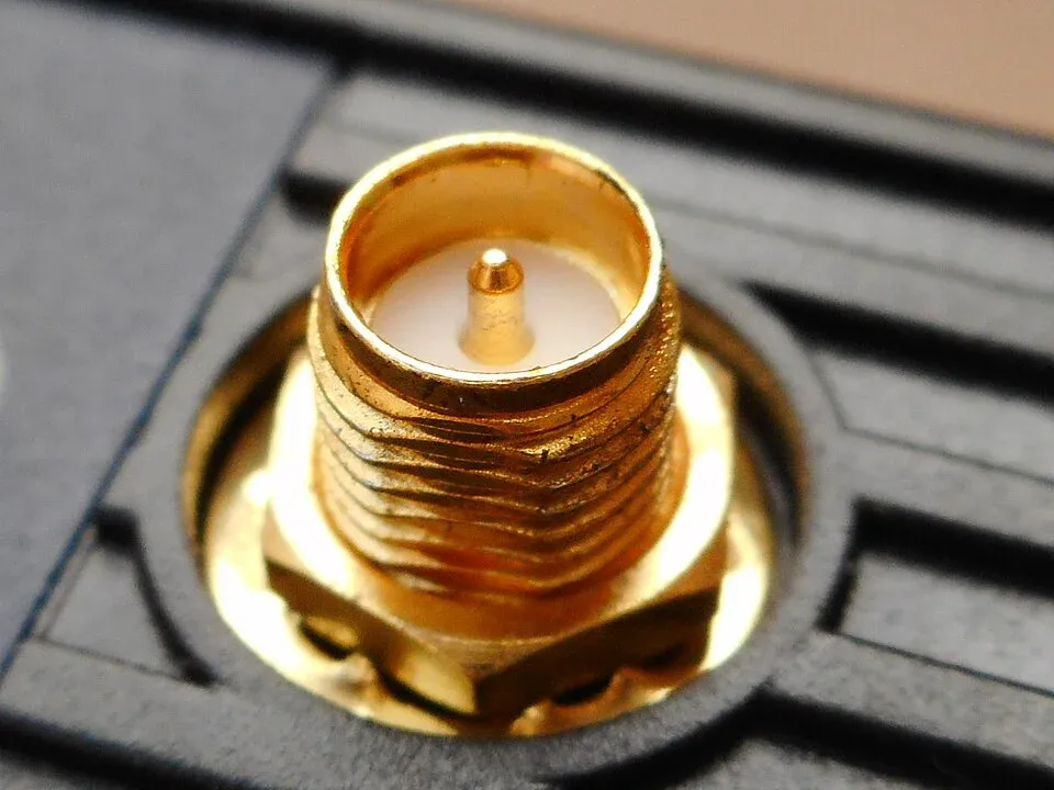
How can you distinguish SMA from RP-SMA?
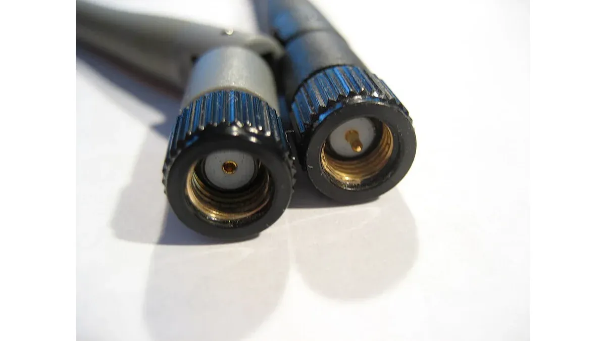
Identify the coupling body’s thread orientation and the center contact independently. Reverse-polarity SMA changes the center contact relative to conventional SMA; it does not mean the RF signal is electrically inverted.
| Interface | Coupling body | Center contact |
|---|---|---|
| SMA plug | Internally threaded coupling nut | Pin |
| SMA jack | Externally threaded body | Socket |
| RP-SMA plug | Internally threaded coupling nut | Socket |
| RP-SMA jack | Externally threaded body | Pin |
Amphenol RF’s RP-SMA family description explains the reversed contact arrangement. Use the exact product drawing to resolve a supplier’s terminology, especially when a quotation uses “male” or “female” without identifying the contact.
A useful receiving photograph shows the mating face clearly enough to see the pin or socket as well as the threads. A side view of a cable connector may establish neither. Keep the photograph associated with its part number and drawing revision; do not approve the entire family from a single sample image.
Does a connector that screws on provide a valid RF connection?
No. Thread engagement establishes only part of the mechanical interface. The center contacts must mate correctly, and the connector, termination and transmission line must meet the electrical requirements of the assembly.
A mismatched contact pair can leave two sockets without a connection or bring two pins into interference. Stop the mating check when the drawing or contact inspection disagrees; tightening harder is not an acceptance test.
Impedance is a separate field. The Amphenol RF SMA family is a 50 Ω connector system, but the frequency capability of a purchase depends on the particular part and its termination. A family headline does not establish the performance of every right-angle body, board launch, adapter or cable assembly.
Also distinguish characteristic impedance from a continuity measurement. A multimeter can detect an open or short; it cannot establish return loss across the required RF band. If a 75 Ω path is involved, specify and assess the actual transition rather than assuming a visually similar assembly is equivalent.
What should an RF connector purchase specification contain?
Include the exact mating interfaces at both ends, impedance, operating frequency band, cable or PCB termination, mechanical constraints and required electrical evidence. The specification should make the supplier’s proposed construction reproducible.
For a cable assembly, an effective line description includes:
- Manufacturer and complete connector code for each end, with SMA or RP-SMA explicitly stated.
- Cable designation, impedance, finished length and dimensional reference points.
- Straight or angled geometry, mounting hardware and allowable bend envelope.
- Required insertion-loss and return-loss or voltage standing-wave ratio limits over a stated band.
- Relevant environmental and handling conditions, with the agreed inspection or test report scope.
These fields are an editorial procurement checklist, not a claim that every application requires the same testing. A short internal jumper and an exposed antenna feed can have different environmental and mechanical needs. State the difference in the order rather than asking a supplier to infer it from the connector name.
Verify the complete assembly at the intended reference planes
When RF measurements are required, define where the measurement starts and ends. Results that include extra adapters or test leads cannot be compared blindly with a limit defined for the cable alone. Retain the measurement setup, calibration context and assembly identity with the report.
The mechanical review should include tool access, bulkhead thickness, cable strain and the space available for the coupling nut. Installation torque comes from the exact manufacturer’s guidance, not from a generic SMA value applied to every product.
The separate connector alternate qualification guide covers contact finishes and mating-life evidence. Those checks complement RF identity and performance; they do not establish that an SMA/RP-SMA combination is the correct mating pair.
Frequently Asked Questions (FAQ)
Does a right-angle SMA connector have the same performance as a straight version?
Do not assume so. Use the specifications for the exact geometry and assembly, including frequency range, return loss or VSWR, and the cable or board transition.
Can an SMA adapter solve every connector mismatch?
An adapter can connect compatible interfaces, but adds an RF transition, insertion loss and mechanical length. Evaluate the complete path and installation rather than treating the adapter as electrically invisible.
Should an RF cable assembly be purchased only by connector name and length?
No. Specify both end interfaces, cable type, impedance, length tolerance, applicable RF limits and any routing or environmental constraints. Define the length reference points on a drawing.