Table of Contents
- Start With the Cell and Pack Specification
- Select Linear, Buck, Boost, or Buck-Boost Charging
- Decide Whether the System Needs Power-Path Management
- Match the Input Source Without Confusing Charging and USB PD
- Build Temperature and Fault Limits Around the Pack
- Check Termination, Recharge, and Low-Power Behavior
- Qualify the Exact Charger and External Power Stage
Battery charging starts with the cell manufacturer’s limits. The charger IC does not define a safe float voltage, temperature window, or termination current for an arbitrary battery; it implements a profile that the product designer must configure and validate against a specific cell or pack.
The second decision is architectural. A linear charger, switching charger, charger with power-path management, and integrated USB-C charging solution can all claim support for the same chemistry while placing very different limits on input power, heat, system startup, firmware, and component substitution.
Start With the Cell and Pack Specification
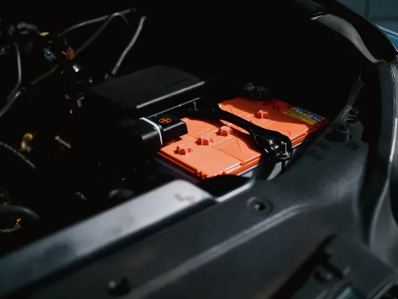
Record chemistry, series and parallel configuration, nominal capacity, maximum charge voltage per cell, permitted charge current, precharge threshold/current, termination method, recharge threshold, allowable charging-temperature range, and any required time limits. Use pack-level values only after confirming how the protection board and cell connections affect sensing.
Cell chemistry labels are not sufficient. Different lithium-ion cathodes and high-voltage variants can have different maximum charge voltages. Lithium iron phosphate uses a different voltage profile from common cobalt-based cells. A charger order code fixed for one regulation voltage cannot be assumed safe for another even when both data sheets say “Li-ion.”
Identify which element provides overvoltage, overcurrent, short-circuit, and overtemperature protection. The charger regulates the intended charge process; the pack protector is an independent last line of protection, and a battery monitor or fuel gauge estimates state. In a multi-cell system, the BMS architecture may also monitor cells and control contactors. These functions should be coordinated, not collapsed into the word “battery management.”
Select Linear, Buck, Boost, or Buck-Boost Charging
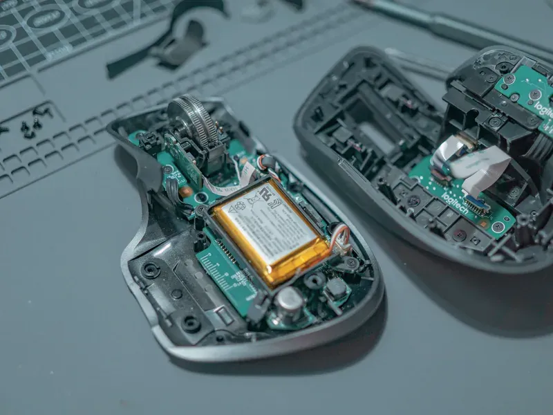
A linear charger drops input voltage across a pass device. It can offer low component count and low switching noise, but its heat is approximately the voltage difference multiplied by charge current. The worst dissipation may occur when the battery is low and the input is high, before the charge current tapers.
A buck charger efficiently steps a higher input down to the pack. A boost charger supports an input below the required pack voltage. A buck-boost charger covers input that can move above and below the pack, which is useful for variable adapters or multi-cell systems but adds power-stage complexity. External FET controllers and integrated-switch chargers also differ in achievable power and thermal placement.
Calculate input and battery power across the full charge cycle and system load, then add conversion loss. Do not select from maximum charge current alone. The TI battery-charger portfolio spans these architectures, while Microchip battery charger ICs include devices with different cell counts, input sources, and integration. Filter by topology only after the pack and source are defined.
Decide Whether the System Needs Power-Path Management
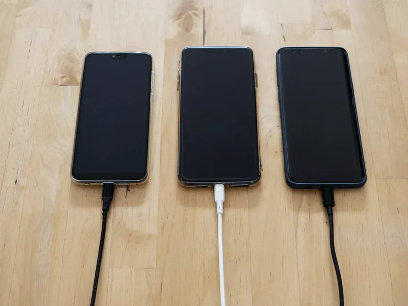
A charger without a managed system path may connect the load so that its current confuses charge termination, slows charging, or causes the product to cycle around a threshold. A power-path charger can prioritize the system, regulate a minimum system rail, allocate remaining input current to the battery, and supplement a weak input from the battery.
Specify what the product must do with no battery, a deeply discharged battery, a full battery, a weak adapter, and a sudden system load. Check minimum system voltage, input-current dynamic power management, supplement-mode thresholds, ideal-diode or reverse-blocking behavior, and battery isolation in ship mode. “Power path” is not one standardized behavior across every vendor.
If the device must boot immediately after an adapter is inserted, verify that the regulated system node can support boot current before the battery rises. If the product must remain off during shipping, calculate total leakage through the charger, pack protector, gauges, pull-ups, and external dividers rather than relying on the charger’s shutdown current alone.
Match the Input Source Without Confusing Charging and USB PD
Define the actual input contract: voltage range, steady and transient current, cable drop, connector rating, source current limit, brownout behavior, and whether the adapter can change voltage. A USB Type-C connector does not by itself grant a high-power contract.
A USB-C Power Delivery controller negotiates roles and power data objects; the charger converts the available power into the battery profile. Some ICs combine these functions, but otherwise firmware or hardware must communicate the negotiated voltage/current limit to the charger. The separate USB-C PD controller selection guide covers that negotiation boundary.
Set input-current limit from the source contract and worst cable conditions. Test what happens when the source collapses, renegotiates, or is unplugged while the system load is active. Reverse current into a disconnected adapter and uncontrolled battery-to-input paths can create safety or connector problems even when the normal charging state works.
Build Temperature and Fault Limits Around the Pack

The product must control charging as cell and board temperatures change. Many charger ICs support a thermistor input and configurable temperature zones; verify the resistor network, threshold tolerance, bias current, open/short detection, and whether the implemented curve matches the cell supplier’s requirements. “JEITA compatible” does not replace a review of actual voltage and current changes in each zone.
Thermal regulation inside the charger can reduce current to protect the IC. That is valuable protection, but it also changes charge time and may indicate inadequate board cooling. Model dissipation at high input, low battery, maximum system load, and restricted airflow. For switch-mode designs, include inductor and external MOSFET losses. TI’s BQ257xx layout guidance shows why high-current paths, sensing, grounding, and switching nodes must be treated as a complete layout problem.
Review input overvoltage, battery overvoltage, charge safety timer, watchdog, thermistor fault, battery short, battery absent, and reverse connection. Determine whether each response is a guaranteed hardware action or depends on host firmware. If a charger has writable limits, define protected startup defaults and the consequence of a stalled host.
Check Termination, Recharge, and Low-Power Behavior
Charge termination often uses taper current, but system load can obscure the battery current if it shares the sensing path. Some products terminate by timer, state machine, or host command. Verify accuracy at the programmed threshold, the minimum current that can be regulated, and conditions that suspend or restart termination.
Recharge hysteresis should prevent rapid cycling while keeping the battery within the product’s availability target. Consider self-discharge, always-on system load, gauge consumption, and temperature-zone transitions. Check whether the charger periodically wakes to measure the battery and how that affects storage life.
Precharge behavior deserves its own test. A deeply discharged cell may require a small current, but an abnormally low pack can also indicate a damaged cell or tripped protection circuit. Set the timeout and fault response with the cell and safety requirements; do not repeatedly force a pack through precharge without diagnosing why it remains low.
Qualify the Exact Charger and External Power Stage
Build a comparison matrix for chemistry, cell count, regulation-voltage accuracy, charge-current range, input range/current limit, topology, power path, thermistor behavior, termination, watchdog, host interface, ship mode, package, temperature grade, and qualification. Record which limits are programmable and which are fixed by order code.
Substitution often changes more than pinout. Register maps, default limits, ADC scaling, watchdog timing, interrupt behavior, inductor range, compensation, FET drive, and thermal pad requirements can force firmware or PCB changes. A higher maximum current is not an upgrade if the sense range or thermal behavior is wrong at the intended operating point.
Validate the production board with the selected cell/pack and representative input sources. Cover input extremes, cable resistance, system load steps, all temperature zones, deeply discharged and full batteries, source removal, battery removal, thermal regulation, timeout, watchdog, and relevant faults. Measure battery current independently so software-reported telemetry does not become the only evidence.
Control the exact orderable code, programmed configuration, pack part number, NTC network, power-stage components, layout revision, and test conditions in the approval record. That package lets procurement evaluate an alternate without treating a safety-dependent charger as a generic voltage regulator.
Remaining-runtime estimation needs a separate qualification from charging. The battery fuel-gauge guide compares voltage-model and hybrid approaches and explains what to retest when the approved cell changes.
Frequently Asked Questions (FAQ)
Can one lithium battery charger IC be used with any Li-ion cell?
No. The charger must match the cell chemistry, series count, permitted charge voltage and current, precharge and termination conditions, temperature limits, and pack-protection architecture. Similar Li-ion labels do not make cell specifications interchangeable.
What is power-path management in a battery charger IC?
Power-path management controls how input power is divided between the system load and battery, often allowing the product to run while charging and limiting battery discharge into the input. Its minimum system voltage, current sharing, supplement mode, and battery-absent behavior must match the product.
Does a USB-C battery charger IC automatically negotiate USB Power Delivery?
Not necessarily. A charger regulates energy into the battery, while a USB-C Power Delivery controller negotiates the source contract. Some devices integrate both functions, but otherwise the charger must receive the negotiated voltage and current limits from a separate Type-C or PD subsystem.