Table of Contents
- Count Pins, Addresses, and Required Update Rate
- Choose I2C or SPI From the Bus Architecture
- Match Input Thresholds and Output Structure
- Design Interrupts for Recoverable Events
- Control Reset, Power-Up, and Partial Power
- Prevent an I2C Expander From Becoming a Bus Failure Point
- Qualify Pinout, Register Map, and Firmware Together
A GPIO expander adds digital inputs and outputs through a serial bus, but pin count is only the first filter. The expander becomes part of the product’s reset behavior, interrupt path, power sequencing, and firmware. If any of those differ, a “compatible” replacement can change outputs before the host is ready or lose an event the host expected to capture.
Begin with each external signal and its safe state. Then choose the bus and device architecture that can deliver the required latency, electrical drive, event retention, and fault containment.
Count Pins, Addresses, and Required Update Rate
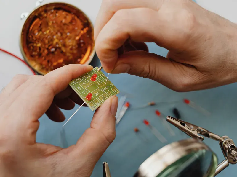
Create an I/O table with direction, voltage domain, input threshold, pull-up or pull-down, output load, default state, update rate, interrupt need, debounce, and behavior while the host resets. Reserve pins for hardware addresses, reset, and interrupt outputs before deciding that an 8-, 16-, or 24-bit expander has enough capacity.
Addressing limits the number of I2C devices on one bus. Check fixed address bits, hardware address pins, alternate order codes, and conflicts with existing sensors or power-management ICs. An I2C multiplexer can add segments but also introduces software, reset, and failure-state considerations. SPI uses chip-select lines or daisy chaining instead of a shared address, which changes both pin count and fault isolation.
Calculate transaction time. A write can include address, register pointer, data, acknowledge bits, and bus overhead; a read may require a pointer write followed by a repeated start and data transfer. If one pin must toggle with microsecond-level certainty, a remote expander behind other bus traffic may be the wrong architecture even when the advertised clock rate appears sufficient.
Choose I2C or SPI From the Bus Architecture
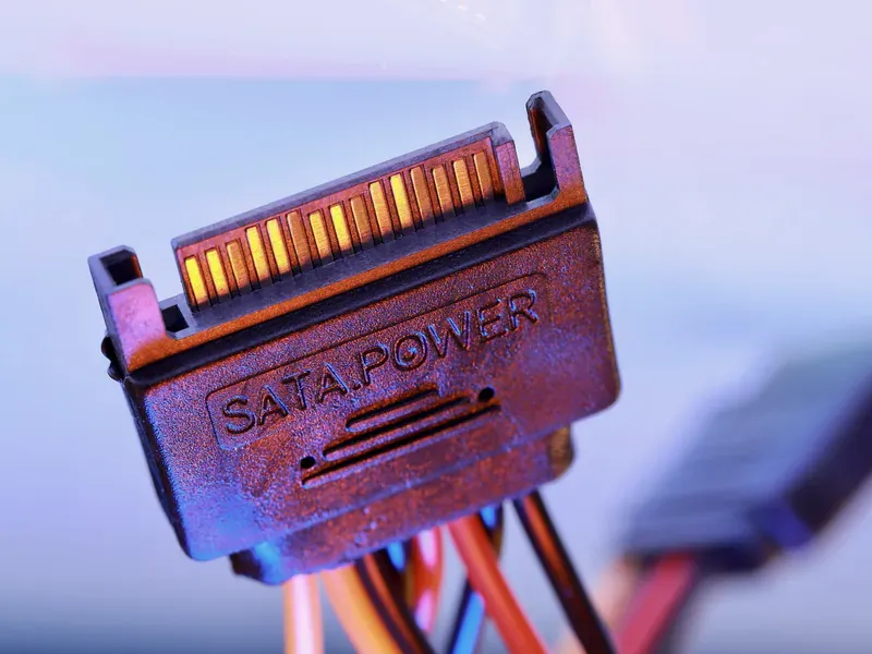
I2C provides addressed communication over two open-drain wires. It works well for moderate-rate configuration and monitoring across several devices, but its pull-ups, capacitance, rise time, clock stretching, arbitration, and stuck-low recovery become system constraints. SPI uses separate clock and data signals plus chip select; it generally offers simpler edge timing and higher throughput at the cost of more wires and no universal acknowledgement convention.
Choose by latency, update pattern, wiring, controller resources, isolation or level-shift needs, cable environment, device count, and failure domain. Do not reduce the decision to “SPI is faster.” A lightly loaded I2C bus can be adequate, while a long or heavily capacitive bus can violate rise-time limits before software bandwidth becomes the problem.
The TI general-purpose I/O portfolio includes I2C and SPI options. Microchip’s MCP23017 data sheet documents one 16-bit I2C implementation with interrupt and reset behavior. Use family resources to build a shortlist, then validate the selected device’s own protocol timing and state machine.
Match Input Thresholds and Output Structure
GPIO pins may be push-pull, open-drain, quasi-bidirectional, input-only, or configurable. A quasi-bidirectional port can use a weak internal source and require a different write/read sequence from a conventional direction register. An open-drain output requires an external pull-up and can only actively pull low. Treat these as different electrical and firmware models.
Compare VIH, VIL, input hysteresis, leakage, pull resistor ranges, output-low voltage at sink current, output-high voltage at source current, and per-pin/total current limits. LED current, relay inputs, optocouplers, FET gates, and logic inputs impose different demands. The package may have a combined ground or supply-current limit below the sum of individual pin ratings.
An expander is not inherently a level translator. Some devices allow GPIOs at a different supply from the serial interface; others use one rail for everything. Power-off tolerance and fail-safe inputs are explicit capabilities. If the I2C bus itself crosses voltages, follow the separate I2C level-shifter selection process.
Design Interrupts for Recoverable Events
An interrupt output reduces polling, but its meaning depends on the device. Some expanders interrupt on any change from the last read, some compare against a programmed default, and others capture the port state at the event. Reading one register may clear the interrupt; a second event during the read can be lost or merged.
For every input event, define whether the system needs the current level, the first captured level, every edge, or only a wake-up indication. Mechanical switches may require hardware or software debounce. Pulse inputs can be shorter than the bus service latency and may need a latch, counter, timer capture, or direct MCU input instead.
Check interrupt output type, polarity, deassertion rule, shared-wire behavior, masking, and reset state. If several expanders share an open-drain interrupt, firmware must identify and service all sources without clearing evidence in the wrong order. Simulate a new event arriving between status reads.
Control Reset, Power-Up, and Partial Power
GPIO outputs should have safe hardware defaults before firmware writes them. Verify the data-sheet reset state for direction, output latch, polarity inversion, pull resistors, interrupt mask, and drive mode. A pin that defaults to input can still float into an active external state unless the board provides a pull resistor.
Determine what resets the part: power-on reset, hardware RESET, software command, bus reset, or none. Check minimum reset pulse, supply ramp, brownout behavior, and register retention. If the host resets without removing expander power, old output latches may remain active; firmware initialization must account for that state.
Analyze partial power. A live external signal or bus pull-up can feed an unpowered expander through its pins. Verify leakage, back-power protection, and whether outputs become high impedance when VCC is absent. Sequence GPIO and bus supplies so that external loads do not activate before the intended control domain is valid.
Prevent an I2C Expander From Becoming a Bus Failure Point
Add the expander’s pin and package capacitance to the complete I2C capacitance budget. Select pull-ups from rise-time and sink-current constraints at the active bus speed. If the design includes level shifters, buffers, hot-swap branches, or long cables, calculate each segment and verify the low-level margin at every device.
Review clock stretching, repeated-start requirements, bus timeout, stuck-SDA/SCL behavior, and reset recovery. Not every I2C expander implements the same optional behaviors. TI’s guide to choosing an I2C device for new designs emphasizes that legacy and newer I2C functions can differ even within apparently similar families.
Firmware should handle a missing acknowledge, interrupted write, stale register cache, expander reset, and host reboot. If outputs control safety-relevant enables, define a hardware safe state that does not depend solely on a successful I2C transaction.
Qualify Pinout, Register Map, and Firmware Together
Build the alternate matrix across package/pinout, supplies, thresholds, output structure, current limits, reset, addresses, protocol speed, register map, interrupt semantics, and temperature grade. A familiar 16-bit pinout does not prove matching polarity, default state, or register order.
The site includes a real route for the Microchip MCP23017-E/ML as one model reference; its presence is not a claim that it is interchangeable with an NXP PCA/PCAL or TI TCA device. Compare exact data sheets and maintain separate drivers or a verified compatibility layer when register behavior differs.
Test all outputs at maximum intended load and all input threshold corners. Exercise simultaneous switching, interrupt races, reset during active outputs, brownout, partial power, bus errors, address conflicts, and recovery. Measure I2C rise/fall and low levels on the production board. Archive the register initialization, driver version, orderable code, and validation log together so procurement cannot change the hardware without the matching software decision.
Frequently Asked Questions (FAQ)
When should a design use SPI instead of an I2C GPIO expander?
SPI is useful when deterministic latency, higher update rate, simpler broadcast timing, or avoidance of I2C addressing and bus-capacitance limits matters more than pin count. I2C is often better when two shared wires and addressable devices are the priority; calculate transaction time and fault behavior for the application.
Are GPIO expanders also voltage level shifters?
Not automatically. The bus pins and GPIO pins have specified input thresholds, output structures, supply domains, and power-off behavior. Some devices support level translation between domains, but many do not, so verify each pin group rather than inferring translation from an I2C interface.
Can two pin-compatible GPIO expanders use the same firmware driver?
Only if their register map, reset values, direction and output-latch semantics, interrupt behavior, polarity controls, addressing, and transaction requirements match. Pin compatibility alone does not establish software compatibility.