Table of Contents
A load switch is the boundary between two power domains. Its on-resistance matters after startup, but its slew-rate control, body-diode path, disable state, and fault response decide whether the system powers up cleanly.
The design task is narrower than selecting an eFuse for fault protection or an ideal-diode controller for ORing. A load switch usually provides controlled connection and disconnection of a low-voltage rail; any protection features must be verified rather than assumed.
How do you choose load-switch rise time from an inrush-current limit?
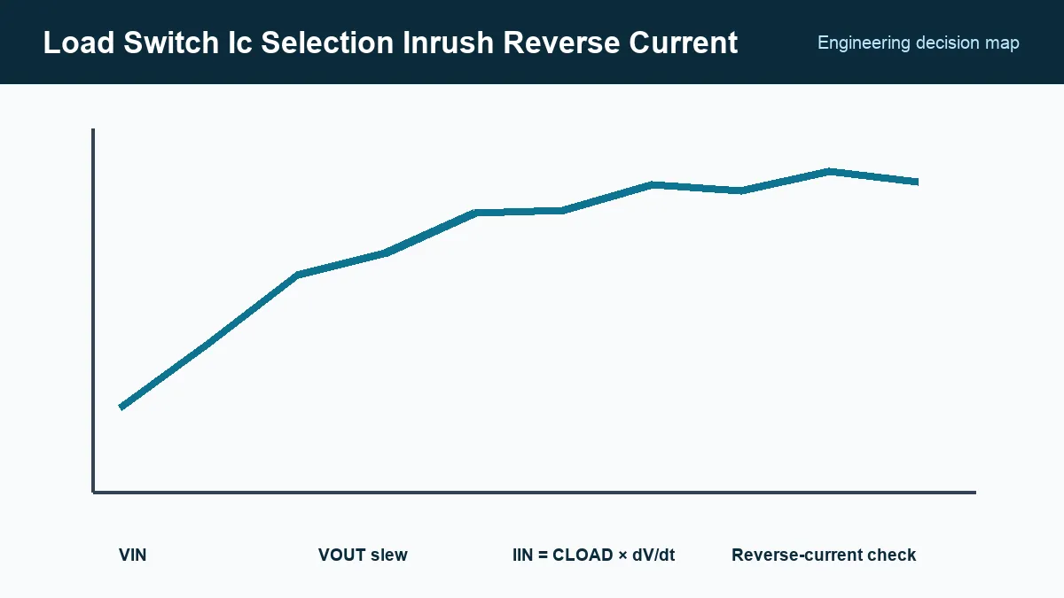
For a roughly linear output ramp, choose a rise time of at least CLOAD × ΔV / IAVAILABLE, where IAVAILABLE is the current left for charging after the operating load is allowed for. This is a first estimate; capacitor tolerance, source impedance, and switch current limiting affect the actual ramp. The underlying relationship is:
IINRUSH = CLOAD × dVOUT/dt
If 100 µF must rise from 0 V to 5 V in 5 ms, the ideal capacitive current is 0.1 A. The actual input current also includes the operating load, capacitor tolerance, leakage, converter startup behavior, and any switch current limit.
Texas Instruments’ load-switch rise-time application report, accessed September 24, 2026, explains the relationship among output capacitance, rise time, and inrush. Use the candidate’s specified rise-time conditions: some devices have fixed slew control, while others use an external capacitor and may behave differently near current limit.
Check the upstream rail’s source impedance and undervoltage behavior. Limiting switch current does not help if the selected threshold repeatedly turns the source or switch off and on, creating a startup oscillation.
Which power-off states can cause a load switch to back-feed?
Check states where the output or downstream I/O remains powered while the load-switch input is absent or lower in voltage. Reverse current may then flow through an internal path or signal-pin protection, depending on the device. Record input, output, enable, and I/O supply combinations, and verify blocking in both enabled and disabled states.
Questions to answer include:
- Can the output be driven above the input by another rail or connector?
- Is reverse current blocked when the switch is on, off, or both?
- Does the device include quick output discharge, and what resistance and current does it present?
- Is the enable pin tolerant when
VINis absent? - Can signal pins back-power the disconnected domain through protection diodes?
The Toshiba load-switch overview, accessed September 24, 2026, distinguishes reverse current, discharge, current limit, and thermal-shutdown behavior. Those functions vary by part; a family label does not guarantee all of them.
Check pass-FET loss and transient stress
Conduction loss is approximately ILOAD² × RON. Use the maximum on-resistance at the applicable input voltage and temperature, then include copper spreading and the package thermal path. A compact switch that looks cool at room temperature can approach thermal shutdown in a sealed product or during a high-current transient.
Current limit may be a protection threshold rather than a precise regulator. Compare its minimum and maximum limits with the load’s startup and fault currents. Also check safe operating behavior during a persistent short: a device can cycle thermally, latch off, or remain current-limited depending on its design.
For capacitive loads, calculate the energy dissipated while the pass FET operates in its linear region. The integrated device datasheet should specify the supported load and startup conditions; do not apply a discrete MOSFET safe-operating-area graph to an internal FET.
How should a load switch sequence power and downstream signals?
Coordinate load-switch enable, output rise, power-good, I/O activity, and discharge so the downstream circuit communicates only in a valid supply state. A slow ramp can hold an MCU, sensor, or radio in an undefined region, while fast output discharge can defeat retention; verify the required sequence with the actual load and upstream supply.
Test normal enable, disable, brownout, rapid re-enable, input removal, output pre-bias, and repeated cycling. Measure VIN, VOUT, input current, enable, and any power-good output on the same time base. Run the test with the maximum production output capacitance and the actual upstream supply.
Release the state table with the part number
An approved load-switch specification should capture voltage range, maximum load current, RON under relevant conditions, controlled rise time, output capacitance, current-limit range, reverse-current behavior, quick-discharge state, enable logic, quiescent/off current, package, and temperature grade.
Attach the verified power-state table and waveforms to the board revision. Procurement can then screen substitutes against explicit behaviors. “Same pinout and lower resistance” is insufficient when the device controls which domain powers first, how much current the source sees, and where charge can flow after shutdown.
Frequently Asked Questions (FAQ)
Can a current-limited load switch still cause startup cycling?
Yes. The upstream supply or switch may repeatedly enter undervoltage or another protection state if charging and operating current prevent the rail from reaching a stable voltage. Test the actual supply, maximum production capacitance, and load startup behavior together.
Does quick output discharge provide reverse-current blocking?
No. Quick output discharge intentionally connects the output to ground when disabled; reverse-current blocking prevents current from flowing from output to input. These are separate functions and must be checked in the exact device datasheet.
Can an eFuse replace a load switch?
Sometimes, but the functions and fault behavior differ. An eFuse may add programmable current limit, overvoltage protection, and fault reporting, while a load switch may prioritize low quiescent current and compact sequencing.