Table of Contents
An LDO regulator is often placed after a battery, DC/DC converter, or shared rail to create a quieter or more tightly controlled supply. Its apparent simplicity hides coupled limits: the input must stay above the output with sufficient headroom, the pass device must dissipate the voltage difference, and the output network must preserve stability while meeting noise and transient requirements.
A useful selection compares the exact operating conditions behind each specification. “Low dropout,” “low noise,” and “high PSRR” can all be true on a product page while none applies at the frequency, load, temperature, or headroom required by the board.
Prove the Input Has Enough Headroom
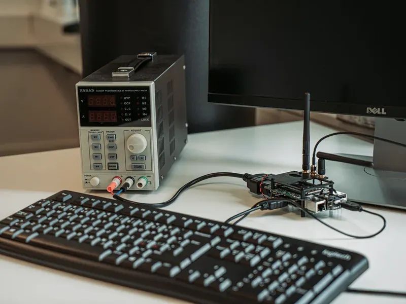
Build a minimum-input budget at the LDO pin. Begin with the upstream source minimum, then subtract connector and trace drop, protection-device loss, cable drop, and the trough of any switching ripple. Compare what remains with output voltage plus dropout at the actual load and temperature.
Dropout is the input-to-output differential at which regulation can no longer maintain the specified output. It is not one universal number for a family. Load current, pass-device architecture, junction temperature, and an optional bias rail can change it. Use maximum or characterized curves appropriate to the exact grade and package, leaving margin for production tolerance and transients.
If a 3.3 V rail falls to 3.1 V at the LDO input while the design expects a regulated 3.0 V output, only 100 mV remains before accounting for ripple, distribution, and dropout. A device promoted with a low typical dropout at light load may not regulate at the required full-load condition.
Also check maximum input, enable voltage, absolute maximum, and startup sequencing. The eFuse selection process covers the upstream fault and inrush behavior; an LDO should not be assigned surge interruption unless its documentation explicitly provides it.
Calculate Dissipation Before Comparing Noise
For a linear regulator, a first estimate of device dissipation is P ≈ (VIN − VOUT) × IOUT, with quiescent and ground-current contributions added when material. A 12 V to 5 V conversion at 200 mA dissipates approximately 1.4 W in the regulator. That may be unreasonable in a small package even though voltage and current are within headline ratings.
Translate dissipation into junction temperature using the manufacturer’s thermal model and the actual PCB. A single junction-to-ambient number may be based on a standardized board unlike the product. Copper area, thermal vias, layer stack, airflow, enclosure, neighboring heat, and duty cycle affect the result.
Review current limit and thermal shutdown as fault protections. They do not guarantee a regulated output or acceptable reliability at a thermally overloaded operating point. If worst-case dissipation is too high, reduce input voltage with a buck converter selected for the full duty-cycle and transient envelope, split the drop, lower current, improve the thermal path, or choose a different architecture.
TI’s LDO Basics guide groups dropout, capacitor selection, thermal management, quiescent current, current limiting, reverse current, PSRR, and noise as separate but related design topics. Use all that apply instead of selecting from one headline metric.
Separate Output Noise from PSRR
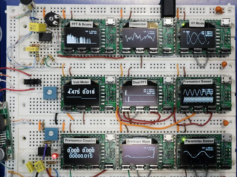
Output noise is generated by the regulator and its reference or internal circuitry. Power-supply rejection ratio (PSRR) describes how much of an input disturbance appears at the output. A low-noise regulator can have modest rejection at a switching frequency, and a regulator with strong low-frequency PSRR can lose rejection at higher frequency.
Define the sensitive load and its frequency range. An ADC reference buffer, RF synthesizer, image sensor, and general MCU rail respond differently to broadband noise, periodic switching ripple, load steps, and startup behavior. Record both integrated-noise bandwidth and spectral density conditions when comparing noise specifications.
For PSRR, compare curves at the intended VIN−VOUT headroom, load, output capacitor, noise-reduction or feed-forward capacitor, and frequency. Rejection commonly changes as the regulator approaches dropout. A “70 dB PSRR” statement without frequency and conditions cannot establish attenuation of a 2 MHz converter ripple.
If a noise-reduction pin or feed-forward capacitor is used, include its startup effect, leakage, tolerance, and layout. Keep the loop small and away from switching nodes. Verify the output spectrum and time-domain response on the final board with measurement bandwidth stated.
Verify Capacitor Range and Loop Stability
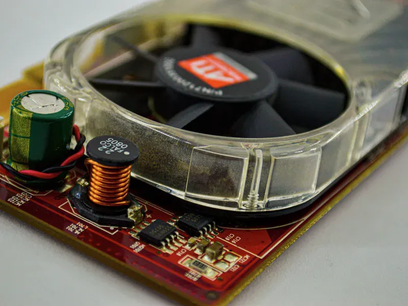
The installed output capacitor is part of the control loop. Check the minimum and maximum effective capacitance, equivalent series resistance (ESR), voltage rating, dielectric, DC-bias derating, temperature, tolerance, and aging against the exact LDO requirements.
A 10 µF ceramic capacitor may provide substantially less effective capacitance at its operating voltage. Conversely, adding excessive capacitance can extend startup, increase reverse-discharge energy, or fall outside a device’s tested range. Input capacitance and source impedance can also produce ringing when the board connects through a cable or hot-plug path.
Use the manufacturer-recommended layout, placing input and output capacitors at the appropriate pins with a short return. Remote bulk capacitance does not replace the local network assumed by the datasheet.
Then test line and load transients at voltage, current, temperature, and capacitor corners. An output that is stable on an evaluation board with one capacitor brand is not proof for a product whose value and ESR differ after bias and temperature.
Check Startup, Reverse Current, and Protection
Define what happens when input rises slowly, enable toggles, output is pre-biased, load comes up in stages, and input collapses while the output capacitor or another rail remains energized. Some LDOs block reverse current; others allow energy to flow from output to input through internal structures. The behavior may change with enable or input voltage.
Soft start or controlled ramp can limit load disturbance but may conflict with processor sequencing or minimum ramp requirements. Power-good thresholds, delay, and validity during brownout must match the supervisor or controller that reads them.
Short-circuit behavior can be a fixed current limit, foldback, hiccup, or thermal cycling. For a fault-sensitive design, capture output current, voltage, temperature, and recovery rather than relying on the presence of an “overcurrent protection” feature.
The Analog Devices LDO guide provides architecture and application context. Apply any equations and recommendations using the selected product’s current documentation and the intended load.
Approve the Exact Suffix and Layout
Compare fixed and adjustable output versions, tolerance grade, package, pinout, enable polarity, output-discharge option, temperature range, qualification, and reel suffix. A family can contain variants with different startup, noise, current, or pin behavior.
Use the TI and Analog Devices directories to organize candidates, then retain the datasheet revision and validation record with the exact code. For an ODM-managed design, put the rail limits, approved capacitors, layout constraints, and substitute-test triggers in the BOM control record.
Final approval should include minimum-input headroom, maximum dissipation, junction-temperature margin, noise and PSRR conditions, capacitor part numbers, line/load transients, startup, shutdown, reverse-current state, and fault recovery. That record prevents a pin-compatible “low-noise LDO” from entering a sensitive rail with untested stability or thermal behavior.
Frequently Asked Questions (FAQ)
Is an LDO's dropout voltage constant across load and temperature?
No. Dropout depends on load current, pass-device architecture, temperature, and sometimes bias supply. Use guaranteed or characterized data at the intended operating points, then include input ripple and distribution loss in the headroom budget.
Does a low-noise LDO automatically have high PSRR?
No. Output noise describes noise generated by the regulator, while PSRR describes rejection of disturbances arriving at the input. Both vary with frequency, load, headroom, capacitors, and device configuration.
Why can an LDO oscillate with a capacitor that has the correct printed value?
The capacitor's effective value can fall with DC bias, temperature, tolerance, and aging, and its ESR may be outside the regulator's stable range. Evaluate the installed capacitor and layout against the exact LDO datasheet.